Do you have a question about the Mitsubishi Electric PUMY-P250YBM2-ER and is the answer not in the manual?
| Model | PUMY-P250YBM2-ER |
|---|---|
| Category | Air Conditioner |
| Type | Heat Pump |
| Cooling Capacity | 25.0 kW |
| Heating Capacity | 28.0 kW |
| Refrigerant | R410A |
| Operating Temperature (Cooling) | -5°C to 46°C |
| Noise Level (Outdoor Unit) | 62 dB(A) |
| Dimensions (Outdoor Unit) | 1338 x 1050 x 330 mm |
| Series | City Multi |
| Power Supply | 380-415V, 50Hz, 3-Phase |
Cautions for units utilizing R410A refrigerant, including repair and piping.
Specific precautions for salt-resistant models to maintain unit performance.
Guidelines for R410A refrigerant piping, including pipe thickness and tools.
Details on connectable indoor units and system configurations.
Describes system construction using branch boxes for connecting indoor units.
Details on mixed system construction connecting various indoor units.
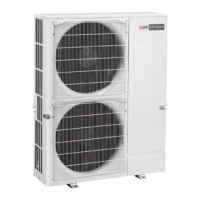
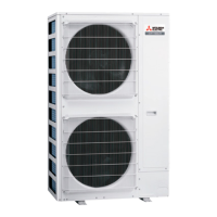
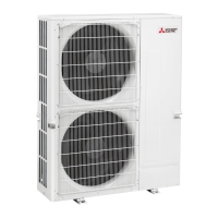
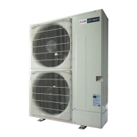
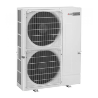
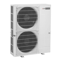
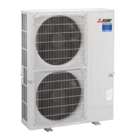
Provides outdoor unit specifications, capacity, and operating temperatures.
Detailed specifications of the PUMY-P250YBM2 and PUMY-P300YBM2 outdoor units.
Guidance on selecting cooling/heating units based on capacity calculations.
Explains capacity correction based on indoor and outdoor temperatures.
Provides capacity diagrams for PUMY-P250YBM2 and PUMY-P300YBM2.
Adjusts capacity based on refrigerant piping length for cooling and heating.
Specifies required free space, service access, and foundation bolt details.
Illustrates piping/wiring directions and pipe knock-out details.
Provides the main power supply wiring diagram for the unit.
Details on transmission system setup, including wiring and addresses.
Illustrates the refrigerant system diagram without a branch box.
Explains connection procedures using 1, 2, or 3 branch boxes.
Details mixed system connections with branch boxes for various indoor units.
Examples of M-NET remote controller system wiring and address setting.
Procedures and checks before unit test run.
Procedure for test run using a wired remote controller.
Troubleshooting steps for errors detected during test run.
Overview of the self-diagnosis function for units and LED indications.
Diagnostic and remedy steps for serial communication errors.
Introduction to electrical wiring for Power Multi series.
Main power supply wiring diagrams and capacity requirements.
Wire cross-sectional areas and breaker capacities for power supply.
Guidance on selecting control wires based on remote controllers and system linkage.
Details on types and wiring examples of transmission cables.
Example wiring diagrams for basic systems with M-NET or branch boxes.
Details on refrigerant piping systems, including line-branch and header-branch methods.
Guidance on selecting refrigerant branch kits based on piping configurations.
Instructions for selecting refrigerant piping diameters for sections.
Procedure for calculating and charging additional refrigerant.
Precautions against R410A refrigerant leakage and room safety.
Steps to confirm R410A concentration and take action.
Step-by-step instructions for outdoor unit disassembly.
Procedure for removing thermistors TH6, TH7, TH4, and TH2.
Steps to remove 4-way valve coil, 4-way valve, and bypass valve.
Procedure for removing high pressure switch, sensors, and low pressure sensor.
Steps to remove linear expansion valves LEV-A and LEV-B.
Procedure for removing reactor components DCL and DCL2.
Step-by-step instructions for compressor removal.
Procedure for removing the accumulator and related parts.
Instructions for removing the compressor protector (TRS).
Explains remote controller buttons and display icons.
Describes display modes (Full, Basic) and status icons.
Details menu structure and settings for operation, comfort, and timers.
Covers test run, maintenance input, settings, error history, and diagnosis.
Covers settings for operation, comfort, timer, energy saving, and restriction.
Covers basic settings, display customization, operation modes, and maintenance.
How to check and reset error codes on the remote controller.
Accessing the service menu for test runs, maintenance input, and settings.
Procedure for performing unit test runs via the remote controller.
Details on setting M-NET address and various operation modes.
How to view and delete error history records from the remote controller.
Procedure for performing self-diagnosis and checking unit status.
Steps to diagnose and check the remote controller's functionality.
Guides for setting up group operations and interlocked LOSSNAY units.