EasyManua.ls Logo

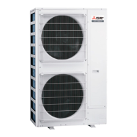
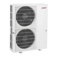
Mitsubishi Electric PUMY-P250YBM2-BS User Manual

Mitsubishi Electric PUMY-P250YBM2-BS
156 pages
To Next Page IconTo Next Page
Page #1 background imageLoading...
Page #1 background image
TECHNICAL & SERVICE MANUAL
OUTDOOR UNIT
HFC
utilized
R410A
PARTS CATALOG (TCB091)
CONTENTS
1. SAFETY PRECAUTION
....................................
2
2. OVERVIEW OF UNITS
......................................
6
3. SPECIFICATIONS
...........................................
10
4. DATA
................................................................
11
5. OUTLINES AND DIMENSIONS
......................
22
6. WIRING DIAGRAM
.........................................
23
7.
NECESSARY CONDITIONS FOR SYSTEM CONSTRUCTION
.....
24
8. TROUBLESHOOTING
....................................
40
9. ELECTRICAL WIRING
...................................
111
10. REFRIGERANT PIPING TASKS
....................
117
11. DISASSEMBLY PROCEDURE
.......................
125
12. REMOTE CONTROLLER
...............................
131
Note:
This service manual
describes technical data of
the outdoor units only.
As for indoor units, refer to its
service manual.
No. TCH091
July 2022
SPLIT-TYPE, HEAT PUMP AIR CONDITIONERS
<Outdoor unit>
[Model Name] Service Ref.
PUMY-P250YBM2
PUMY-P250YBM2.TH
PUMY-P300YBM2
PUMY-P300YBM2.TH
PUMY-P250YBM2-ER
PUMY-P250YBM2-ER.TH
PUMY-P300YBM2-ER
PUMY-P300YBM2-ER.TH
PUMY-P250YBM2-ET
PUMY-P250YBM2-ET.TH
PUMY-P300YBM2-ET
PUMY-P300YBM2-ET.TH
Salt proof model
PUMY-P250YBM2-BS
PUMY-P250YBM2-BS.TH
PUMY-P300YBM2-BS
PUMY-P300YBM2-BS.TH
PUMY-P250YBM2-ERBS
PUMY-P250YBM2-ERBS.TH
PUMY-P300YBM2-ERBS
PUMY-P300YBM2-ERBS.TH
PUMY-P250YBM2-ETBS
PUMY-P250YBM2-ETBS.TH
PUMY-P300YBM2-ETBS
PUMY-P300YBM2-ETBS.TH
Question and Answer IconNeed help?

Do you have a question about the Mitsubishi Electric PUMY-P250YBM2-BS and is the answer not in the manual?

Mitsubishi Electric PUMY-P250YBM2-BS Specifications

General IconGeneral
BrandMitsubishi Electric
ModelPUMY-P250YBM2-BS
CategoryAir Conditioner
LanguageEnglish

Summary

1 SAFETY PRECAUTION

1-1. CAUTIONS RELATED TO NEW REFRIGERANT

Essential precautions for handling new refrigerants like R410A and proper installation practices.

Precautions for Repair Service

Guidelines for safe and effective repair procedures, including preparation and handling of components.

1-3. Cautions for Refrigerant Piping Work

3 Tools for R410A

4-2. CORRECTION BY TEMPERATURE

4-4. CORRECTING CAPACITY FOR CHANGES IN THE LENGTH OF REFRIGERANT PIPING

Capacity Correction Curves for Piping Length

Provides charts to adjust cooling and heating capacity based on equivalent refrigerant piping length.

6 WIRING DIAGRAM

Main Power Supply Wiring Diagram

Illustrates the main power supply wiring for the outdoor unit and its connections.

7 NECESSARY CONDITIONS FOR SYSTEM CONSTRUCTION

8 TROUBLESHOOTING

8-1. CHECKPOINTS FOR TEST RUN

Outlines essential checks and procedures to perform before starting a test run of the system.

8-1-3. Countermeasures for Error During Test Run

Provides detailed steps for diagnosing and resolving various error codes detected during test runs.

Troubleshooting Specific Error Codes

Detailed troubleshooting procedures for a comprehensive list of error codes, from Ed to 7130.

8-4. INTERNAL SWITCH FUNCTION TABLE

8-6. HOW TO CHECK THE PARTS

Thermistor and Solenoid Valve Resistance Checks

Provides resistance values for checking thermistors, solenoid valves, and motors for proper function.

DC Fan Motor and Outdoor Multi Controller Board Checks

Outlines procedures for checking DC fan motor operation, fuses, wiring, and power supply voltages.

9 ELECTRICAL WIRING

9-2-1. Wiring Diagram for Main Power Supply

9-3. DESIGN FOR CONTROL WIRING

9-4. WIRING TRANSMISSION CABLES

9-6. EXAMPLE EXTERNAL WIRING DIAGRAM FOR A BASIC SYSTEM

9-7. METHOD FOR OBTAINING ELECTRICAL CHARACTERISTICS

10 REFRIGERANT PIPING TASKS

10-1. REFRIGERANT PIPING SYSTEM

Covers refrigerant piping system design, including line-branch and header-branch methods, and permissible lengths.

10-2. PRECAUTIONS AGAINST REFRIGERANT LEAKAGE

11 DISASSEMBLY PROCEDURE

11-1. OUTDOOR UNIT DISASSEMBLY

Provides step-by-step instructions and figures for disassembling the outdoor unit components.

12 REMOTE CONTROLLER

12-2. ERROR INFORMATION

Describes how to check and reset error codes displayed on the remote controller, including contact information.

12-3. SERVICE MENU ACCESS AND OPERATION

Guides on accessing the service menu, entering passwords, and navigating through maintenance functions.

12-4. TEST RUN OPERATIONS

Details how to perform test runs for cooling, heating, and auto vane functions using the remote controller.

12-5. FUNCTION SETTING PROCEDURES

Explains how to configure M-NET addresses, function numbers, and other settings via the remote controller.

12-6. ERROR HISTORY MANAGEMENT

Covers how to view and delete error history records from the remote controller.

12-7. SELF-DIAGNOSIS PROCEDURES

Outlines steps for performing self-diagnosis on the remote controller and checking unit status.

12-8. REMOTE CONTROLLER CHECK

Provides a method to diagnose and check the remote controller's functionality and communication.

12-9. SPECIAL FUNCTION OPERATION SETTING

Explains how to set special functions like group settings and Lossnay interlocking via the remote controller.

Related product manuals