Do you have a question about the Mitsubishi Electric PUMY-P36NKMU3 and is the answer not in the manual?
| Refrigerant | R410A |
|---|---|
| Outdoor Unit Noise Level | 58 dB(A) |
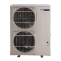
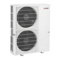
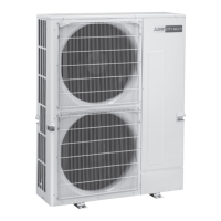
| Series | PUMY |
| HSPF | 3.80 |
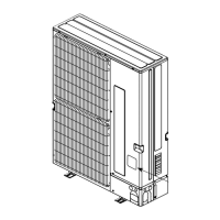
| Dimensions (Indoor Unit) | 200 mm |
| Coefficient of Performance (Heating) | 4.0 |
Essential safety practices before and during repair service.
Guidelines for using R410A refrigerant and necessary tools.
Specific installation and maintenance advice for salt-proof models.
Configuration for auxiliary heating function and indoor fan speed during defrost.
Explanation of how to identify MULTI-S model outdoor units based on their naming convention.
Specifies the operational temperature limits for cooling and heating modes.
Flowchart and method for selecting compatible indoor and outdoor units based on capacity.
Charts for adjusting cooling/heating capacity based on temperature variations.
Provides reference data for standard operation conditions of various models.
Diagrams for calculating system capacity based on total indoor unit capacity.
Curves for adjusting capacity based on equivalent piping length.
Octave band sound pressure levels for different models during cooling and heating.
Guidelines for setting up the transmission system, including wiring and address settings.
Diagrams illustrating the refrigerant flow and components of the system.
Examples of M-NET and MA remote controller system configurations and address settings.
Procedures and checks to perform before conducting a test run of the system.
Lists error codes and their corresponding causes and corrective measures.
Flowcharts for diagnosing specific system errors using self-diagnosis functions.
Lists normal system behaviors that may appear as errors but are not actual malfunctions.
Table detailing the functions of internal switches on the outdoor unit for various settings.
Diagrams and descriptions of connectors and their functions on the outdoor unit.
Guides on checking the resistance and specifications of individual components.
Diagrams showing test points for diagnosing electrical issues on various circuit boards.
Table explaining the display modes and functions related to diagnostic codes and unit status.
General notes and precautions regarding power wiring for the system.
Wiring diagrams and specifications for main power supply and capacity calculations.
Information on selection and types of control wires for remote controllers and system linking.
Details on the types and specifications of transmission cables used for system communication.
Explanation of system switch settings for identifying unit destinations and addresses.
A basic wiring diagram illustrating a system using an M-NET controller.
Procedures for calculating electrical characteristics for power company agreements.
Details on refrigerant piping system design, including length, diameter, and branch kits.
Guidelines and procedures to prevent refrigerant leakage and ensure safe concentration levels.