Do you have a question about the Mitsubishi Electric PUMY-P36NKMU4 and is the answer not in the manual?
| Brand | Mitsubishi Electric |
|---|---|
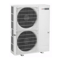
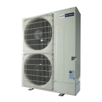
| Model | PUMY-P36NKMU4 |
| Category | Air Conditioner |
| Language | English |
Essential safety rules to follow before and during repair service.
Specific precautions for handling R410A refrigerant and related piping.
Details on setting up auxiliary heating control and indoor fan speed during defrost mode.
Information on connectable indoor units and system configuration based on outdoor unit models.
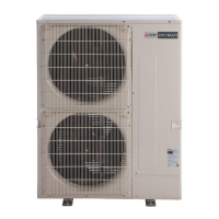
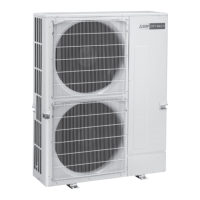
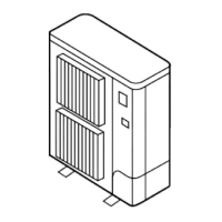
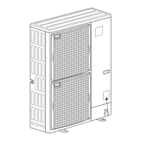
Detailed technical specifications for outdoor units including capacity, power, and dimensions.
Flowchart for determining indoor/outdoor unit capacity based on load and temperature conditions.
DIP switch settings for model selection on the outdoor unit's multi-controller board.
Details on M-NET cable connections, addresses, and wiring for system setup.
Procedures and safety checks to perform before conducting a test run.
Troubleshooting guide for error codes detected during test runs, with corrective actions.
Flowcharts to diagnose and resolve specific errors like serial communication issues.
General notes and precautions for power wiring and connections.
Wiring diagrams and capacity information for main power supply.
Details on refrigerant piping systems, diameter selection, and branch kits.
Guidelines for calculating and adding refrigerant for extended piping lengths.
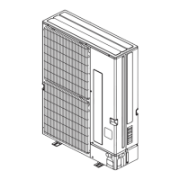
Steps to remove exterior panels and the fan motor assembly.
Procedure for safely disconnecting and removing the electrical parts box.
Instructions for removing the 4-way valve coil and related parts.
Instructions for removing key internal components like compressor and accumulator.
Procedure for changing the fusible plug and removing the thermal protector.
Explanation of the remote controller interface, buttons, and display icons.
How to view and reset error codes displayed on the remote controller.
Procedures for performing test runs of cooling, heating, and vane operations.
Guide to performing self-diagnosis and checking error history via the remote controller.