EasyManua.ls Logo

Mitsubishi Electric PUMY-P60NKMU1 User Manual

Mitsubishi Electric PUMY-P60NKMU1
126 pages
To Next Page IconTo Next Page
Page #1 background imageLoading...
Page #1 background image
PARTS CATALOG (OCB613)
CONTENTS
1. SAFETY PRECAUTION
.....................................
2
2. OVERVIEW OF UNITS
.......................................
5
3. SPECIFICATIONS
............................................
10
4. DATA
.................................................................
11
5. OUTLINES AND DIMENSIONS
.......................
24
6. WIRING DIAGRAM
...........................................
25
7.
NECESSARY CONDITIONS FOR SYSTEM CONSTRUCTION
.......
26
8. TROUBLESHOOTING
......................................
36
9. ELECTRICAL WIRING
...................................
111
10. REFRIGERANT PIPING TASKS
....................
116
11. DISASSEMBLY PROCEDURE
.......................120
No. OCH613
REVISED EDITION-B
HFC
utilized
R410A
February 2018
SPLIT-TYPE, HEAT PUMP AIR CONDITIONERS
Note:
This service manual describes
technical data of the outdoor
units only.
[Service Ref.]
PUMY-P60NKMU1
PUMY-P60NKMU1-BS
<Outdoor unit>
[Model name]
PUMY-P60NKMU1
Salt proof model
PUMY-P60NKMU1-BS
TECHNICAL & SERVICE MANUAL
OUTDOOR UNIT
Model name
indication
Revision:
Corrected some descrip-
tions in "4-2. CORRECTION
BY TEMPERATURE" in
REVISED EDITION-B.
Some other descriptions
have been also modified.
OCH613 REVISED EDITION-B
is void.
Question and Answer IconNeed help?

Do you have a question about the Mitsubishi Electric PUMY-P60NKMU1 and is the answer not in the manual?

Mitsubishi Electric PUMY-P60NKMU1 Specifications

General IconGeneral
BrandMitsubishi Electric
ModelPUMY-P60NKMU1
CategoryAir Conditioner
LanguageEnglish

Summary

Safety Precautions for R410A Refrigerant

Cautions for New Refrigerant Handling

Precautions for using R410A refrigerant, tools, and piping.

Precautions for Salt Proof Models

Guidelines for installing and maintaining salt-proof unit models.

General Service and Tool Requirements

Covers general service cautions and specific tools for R410A.

Refrigerant Piping Work Cautions

Pipe Thickness and Flare Dimensions

Specifies required pipe thickness and dimensions for R410A flare connections.

R410A Tools Compatibility

Table indicating compatibility of R22/R407C tools with R410A.

Unit Overview and Specifications

Auxiliary Heating Control Setup

Instructions for setting up auxiliary heating and fan speed control.

Outdoor Unit Specifications

Details outdoor unit specifications including capacity and temperature ranges.

System Specifications and Data

Detailed Unit Specifications

Comprehensive list of technical specifications for the unit.

Cooling and Heating Unit Selection Data

Flowchart for selecting indoor/outdoor units based on capacity.

Temperature Correction Curves

Cooling Capacity Correction

Correction curves for cooling capacity based on temperature.

Heating Capacity Correction

Correction curves for heating capacity based on temperature.

Standard Operation and Capacity Data

Standard Operation Reference Data

Table of standard operating data under various conditions.

Standard Capacity Diagrams

Capacity diagrams for cooling and heating based on indoor unit capacity.

Refrigerant Piping Capacity Correction

Capacity Correction Curves by Piping Length

Curves showing capacity correction based on equivalent piping length.

Heating Capacity Correction for Frost/Defrost

Correction factors for heating capacity due to frost or defrosting.

Unit Dimensions and Installation

Outlines and Dimensions

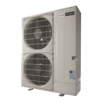
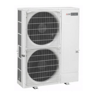
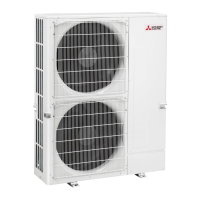
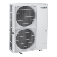
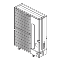
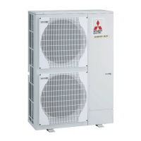
Overall dimensions and external views of the unit.

Installation Clearances and Foundation

Required free space, service space, and foundation bolt details.

Wiring Diagrams and System Control

Outdoor Unit Wiring Diagram

Detailed wiring diagram for the outdoor unit.

System Control and Transmission Setup

Conditions for system construction and transmission setup.

Troubleshooting Guide

Test Run Procedures and Checks

Points to check and procedures before initiating a test run.

Error Code Diagnosis: Serial Communication

Troubleshooting flowchart for serial communication errors (0403).

Error Code Diagnosis: Compressor Temperature

Troubleshooting flowchart for compressor temperature issues (1102).

Error Code Diagnosis: High Pressure Trouble

Troubleshooting flowchart for high pressure errors (1302).

Component Checks and Troubleshooting

Thermistor Resistance Charts

Charts showing thermistor resistance vs. temperature.

Checking Pressure Sensors

Procedures for comparing high and low pressure sensor readings.

Outdoor Unit Circuit Board Checks

Methods for checking multi and power circuit boards.

Electrical Wiring and System Setup

Power Wiring Overview

Introduction to power wiring requirements and notes.

Transmission Cable Types and Wiring

Details on transmission cable types, M-NET, and MA remote control cables.

System Switch Settings

Procedure for assigning identification numbers (addresses) via switches.

Refrigerant Piping and Leakage Precautions

Refrigerant Piping System

Overview of refrigerant piping, branch kits, and charge calculations.

R410A Leakage Precautions

Precautions against refrigerant leakage and confirming R410A concentration.

Disassembly Procedure

Removing Panels and Fan Motor

Steps to remove the service panel, top panel, and fan motor.

Removing Electrical Components

Steps to remove electrical parts box, thermistors, and valves.

Removing Compressor and Accumulator

Steps to remove the compressor and accumulator.

Related product manuals