EasyManua.ls Logo

Mitsubishi Electric PUMY-P60NKMU2 User Manual

Mitsubishi Electric PUMY-P60NKMU2
148 pages
To Next Page IconTo Next Page
Page #1 background imageLoading...
Page #1 background image
TECHNICAL & SERVICE MANUAL
OUTDOOR UNIT
No. OCH695
REVISED EDITION-B
HFC
utilized
R410A
June 2021
Note:
This service manual
describes technical data of
the outdoor units only.
Revision:
Precaution in 1. SAFETY
PRECAUTION has been
added in REVISED
EDITION-B.
<Outdoor unit>
[Model Name]
Model name
indication
PARTS CATALOG (OCB695)
PUMY-P36NKMU2
PUMY-P48NKMU2
PUMY-P60NKMU2
PUMY-HP36NKMU
PUMY-HP48NKMU
PUMY-P36NKMU2-BS
PUMY-P48NKMU2-BS
PUMY-P60NKMU2-BS
Salt proof model
PUMY-P36NKMU2
PUMY-P48NKMU2
PUMY-P60NKMU2
PUMY-HP36NKMU
PUMY-HP48NKMU
PUMY-P36NKMU2-BS
PUMY-P48NKMU2-BS
PUMY-P60NKMU2-BS
[Service Ref.]
SPLIT-TYPE, HEAT PUMP AIR CONDITIONERS
OCH695A is void.
CONTENTS
1. SAFETY PRECAUTION ·······················2
2. OVERVIEW OF UNITS ························5
3. SPECIFICATIONS ···························· 10
4. DATA ·············································· 12
5. OUTLINES AND DIMENSIONS ··········· 32
6. WIRING DIAGRAM ··························· 34
7. NECESSARY CONDITIONS
FOR SYSTEM CONSTRUCTION ········· 37
8. TROUBLESHOOTING ······················· 48
9. ELECTRICAL WIRING ·····················124
10. REFRIGERANT PIPING TASKS ·········129
11. DISASSEMBLY PROCEDURE ···········136

Other manuals for Mitsubishi Electric PUMY-P60NKMU2

Question and Answer IconNeed help?

Do you have a question about the Mitsubishi Electric PUMY-P60NKMU2 and is the answer not in the manual?
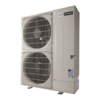
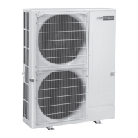
Mitsubishi Electric PUMY-P60NKMU2 Specifications

General IconGeneral
ModelPUMY-P60NKMU2
TypeHeat Pump
Cooling Capacity60, 000 BTU/h
Heating Capacity68, 000 BTU/h
Energy Efficiency Ratio (EER)10.5
RefrigerantR410A
Power Supply208 / 230V, 1 Phase, 60 Hz
Operating Temperature Range (Cooling)23° to 115°F (-5° to 46°C)
Operating Temperature Range (Heating)-4° to 70°F (-20° to 21°C)
Outdoor Unit Weight203 lbs (92 kg)

Summary

1 SAFETY PRECAUTION

1-1. CAUTIONS RELATED TO NEW REFRIGERANT

Precautions for R410A refrigerant, required tools, and piping guidelines.

Preparation before the repair service

Lists necessary steps and checks before commencing repair work.

Precautions during the repair service

Details critical safety measures to be observed while performing repairs.

3 SPECIFICATIONS

4 DATA

4-1. SELECTION OF COOLING/HEATING UNITS

Guide for selecting appropriate indoor and outdoor units based on capacity.

4-2. CORRECTION BY TEMPERATURE

Adjustments to cooling/heating capacity and power input based on temperature.

4-4. STANDARD CAPACITY DIAGRAM

Charts for adjusting capacity based on total indoor unit capacity.

4-5. CORRECTING CAPACITY FOR CHANGES IN THE LENGTH OF REFRIGERANT PIPING

Adjustments to capacity based on refrigerant piping length.

6 WIRING DIAGRAM

8 TROUBLESHOOTING

8-1. CHECKPOINTS FOR TEST RUN

Steps to follow before and during test runs for system verification.

8-1-1-2. Test run for wired remote controller <PAR-3*MAA>

Specific test run procedure for a wired remote controller.

8-1-2. Countermeasures For Error During Test Run

Solutions and actions for various error codes detected during test runs.

8-1-3. SELF-DIAGNOSIS ACTION BY FLOWCHART

Troubleshooting flowcharts for diagnosing system errors.

8-5. INTERNAL SWITCH FUNCTION TABLE

9 ELECTRICAL WIRING

10 REFRIGERANT PIPING TASKS

10-2. PRECAUTIONS AGAINST REFRIGERANT LEAKAGE

11 DISASSEMBLY PROCEDURE

13. Removing the compressor (MC)

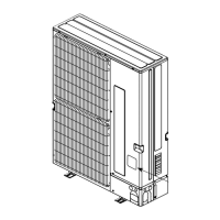
Detailed steps for removing the compressor unit.

Related product manuals