Do you have a question about the Mitsubishi Electric PUMY-P300YBM2.TH and is the answer not in the manual?
| Cooling Capacity | 30.0 kW |
|---|---|
| Heating Capacity | 33.5 kW |
| Refrigerant | R410A |
| Operating Temperature (Cooling) | -5°C to 46°C |
| Power Supply | 3-phase, 380-415V, 50Hz |
| Indoor Unit Compatibility | Compatible with various indoor units |
Provides essential precautions for handling the new R410A refrigerant during installation and maintenance.
Outlines necessary steps and tools required before commencing any repair or maintenance work on the unit.
Details critical safety measures to follow while performing repairs or inspections on the unit's components.
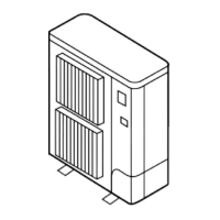
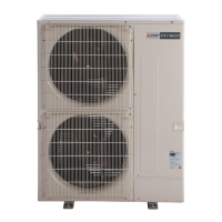
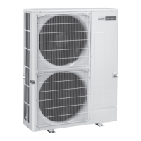
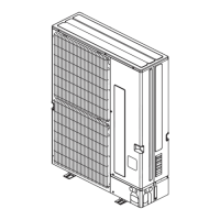
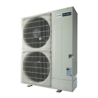
Provides detailed specifications for the outdoor units, covering power, capacity, dimensions, and components.
Lists essential checks and procedures to perform before initiating a test run of the air conditioning system.
Guides users on how to perform a test run using a wired remote controller, referring to specific section 12-4.
Provides troubleshooting steps and corrective actions for errors detected during the test run, identified by code numbers.
Provides a step-by-step guide for checking the DC fan motor, including fuse, wiring, and power supply.
Presents thermistor feature charts with resistance values at different temperatures for low temp thermistors.
Explains how to compare high pressure sensor readings with gauge pressure and configure diagnostic settings.
Explains how to compare low pressure sensor readings with gauge pressure and configure diagnostic settings.
Presents a thermistor feature chart with resistance values at different temperatures for the medium temp thermistor.
Presents a thermistor feature chart with resistance values at different temperatures for the high temp thermistor.
Shows schematic drawings for main power supply wiring, distinguishing between systems with and without branch boxes.
Details the line-branch method for refrigerant piping, including permissible lengths and connection examples.
Details the header-branch method for refrigerant piping, including permissible lengths and connection examples.
Explains refrigerant piping for branch box systems, including permissible lengths and selecting piping diameters.
Guides on calculating additional refrigerant charge for branch box systems based on piping and capacity.
Provides methods to calculate and charge additional refrigerant based on piping length, capacity, and unit type.
Provides a procedure to calculate and confirm R410A concentration in rooms to prevent potential injury.
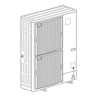
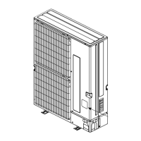
Provides a general overview of the disassembly procedure for the outdoor unit, noting power-off requirement.
Provides instructions for removing the compressor, including felt covering, thermistor, protector, and wiring.
Guides on removing the accumulator, including its inlet/outlet pipes and leg fixing screws.
Guides on how to check error codes, unit details, and reset errors using the remote controller interface.
Explains how to access and view error information from the Maintenance menu, noting that errors cannot be reset from this screen.
Details how to access the service menu, enter the maintenance password, and navigate its options.
Guides on performing a test run for the PAR-4xMAA controller, including checking cooling, heating, and fan operations.
Provides instructions for performing a test run using the PAR-SL97A-E remote controller, including mode selection and checks.
Details the steps for performing a test run with the PAR-SL100A-E remote controller, including mode selection and unit checks.
Explains how to perform a test run using the PAR-U02MEDA controller, including monitoring operating status and unit settings.
Guides on setting functions like M-NET address, function number, and data for the PAR-4xMAA remote controller.
Details the function selection process for the PAR-SL97A-E controller, including unit number, mode, and setting selection.
Provides instructions for setting functions on the PAR-SL100A-E controller, covering unit number, mode, and setting selection.
Guides on how to view the error history and delete recorded errors using the remote controller's Check menu.
Details the steps for performing self-diagnosis on the PAR-4xMAA controller, including M-NET address entry and error history reset.
Explains the malfunction diagnosis method for the PAR-SL97A-E controller, including error code display and check procedures.
Guides on performing self-diagnosis for the PAR-SL100A-E controller, including checking refrigerant address and operation status.
Provides a procedure to diagnose the remote controller's functionality, check for errors, and interpret results.