1
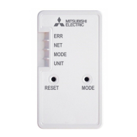
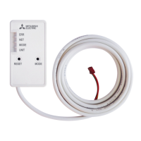
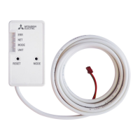
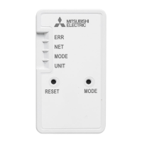
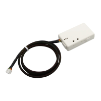
RMF-CA100-V1 Thermostat Interface
INSTALLATION / INSTRUCTION MANUAL
Read prior to installing/operating device. Keep this manual for future reference.
1.
Supplied Parts. ........................................................................... 1
2.
Safety Precautions. .................................................................... 1
3. Installation ....................................................................................... 1
4. System Configuration ...................................................................... 3
5.
Operator Instructions .................................................................. 3
RMF-CA100-V1 Thermostat Interface (1)
RMF-CA100 Manual (1)
THOROUGHLY READ THE FOLLOWING SAFETY PRECAUTIONS BEFORE EACH USE OF THIS PRODUCT (THE “DEVICE”).
•
Do not expose the device to, or immerse the device in, water.
Doing so could lead to electrical shock to a person, device malfunction or
device damage.
•
Do not install the device in a
bathroom, kitchen, or any room
where steam could form.
Condensation could develop on or around the device and
cause
electrical shock to a person, device malfunction and device damage.
•
Do not install the device in a
location where a gas leak
could occur.
•
Do not expose the device to heat or radiation, including direct sunlight, or install the device in a
location where the temperature
could be greater
than 40°C
(104°F) or less than 0°C (32°F). Doing any of these things could result in device deformation or
device
malfunction.
•
Always ensure the device is installed in an area without exposure to high frequency noise.
•
Power generators, inverters,
and
high-frequency or radio
communication equipment may
interfere with the operation of
this device.
•
All electrical work should be
performed by a qualitied technician and in accordance with applicable laws and the instructions
outlined in this
manual.
•
Use standard wiring with the proper
current capacity to avoid current leak,
excessive heat, and fire.
•
Use only specified cables and wiring;
securely connect each so that
the terminals do not bear any weight.
•
Include slack in the power
supply wiring.
Tension in the wiring may cause it to excessively heat up and break,
which could
result in a fire.
•
Improperly connected or short-circuited
cables or wiring may produce heat and cause device malfunction, device damage, and
fire.
•
Capacity shortage to the power supply
circuit or improper installation may
result in electrical shock or fire.
•
Do not modify or
alter this device or cable in any manner whatsoever.
Thermostat may be configured for use with a conventional system. For mode settings please refer to
WWW.MITSUBISHITECHINFO.CA website M & P Series Indoor Unit Function Mode Setting chart in Application / Misc section
•
Make all connections with
18 AWG
thermostat wire.
•
Wire connection terminals support 20-30VAC.
•
High/medium/low fan signals
(G1, G2, G3)
are optional, and may not be available on all
thermostat models.
•
Auxiliary heat control is not controlled by the RMF-CA100. Auxiliary heat control remains with Mitsubishi CN24
connector on compatible indoor units.
MODE SELECTION
1. Select 1 or 2 stage thermostat operation using dipswitch 1-1:
OFF position (default)
In the OFF position RMF-CA100 configures for 2 stage heating and cooling thermostats (Y1, Y2 & W1, W2)
WARNING - INCORRECT HANDLING CAN RESULT IN ELECTRICAL INJURY, DEVICE MALFUNCTION AND DAMAGE