EasyManua.ls Logo

Mitsubishi Electric SLZ-KF25VA2 User Manual

Mitsubishi Electric SLZ-KF25VA2
34 pages
To Next Page IconTo Next Page
Page #1 background imageLoading...
Page #1 background image
TECHNICAL & SERVICE MANUAL
CONTENTS
1. REFERENCE MANUAL
......................
2
2. SAFETY PRECATION .........................2
3. PARTS NAMES AND FUNCTIONS
.....
4
4. SPECIFICATIONS
...............................
9
5. OUTLINES AND DIMENSIONS
.........
11
6. WIRING DIAGRAM
............................
13
7.
REFRIGERANT SYSTEM DIAGRAM
.....
14
8. TROUBLESHOOTING
.......................
15
9. 4-WAY AIR FLOW SYSTEM
..............
28
10. DISASSEMBLY PROCEDURE
..........
30
No. OCH616
Indoor unit
[Model Name] [Service Ref.]
SLZ-KF25VA2.TH
SLZ-KF25VA2.TH-ER
SLZ-KF35VA2.TH
SLZ-KF35VA2.TH-ER
SLZ-KF50VA2.TH
SLZ-KF50VA2.TH-ER
SLZ-KF60VA2.TH
SLZ-KF60VA2.TH-ER
INDOOR UNIT
Model name
indication
SLZ-KF25VA2
SLZ-KF35VA2
SLZ-KF50VA2
SLZ-KF60VA2
March 2016
Note:
• This manual describes service
data of the indoor units only.
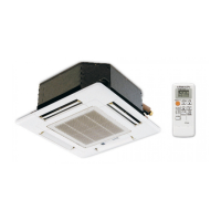
WIRED REMOTE CONTROLLER
(Option)
PARTS CATALOG (OCB616)
SPLIT-TYPE, HEAT PUMP AIR CONDITIONERS
WIRELESS REMOTE
CONTROLLER
(Option)
Questions and Answers:

Mitsubishi Electric SLZ-KF25VA2 Specifications

General IconGeneral
Cooling Capacity2.5 kW
Heating Capacity3.2 kW
Power Supply220-240 V, 50 Hz
Indoor Unit Dimensions (WxHxD)570 x 256 x 570 mm
Indoor Unit Weight14 kg
Outdoor Unit Dimensions (WxHxD)800 x 550 x 285 mm
Outdoor Unit Weight31 kg
RefrigerantR32

Summary

Safety Precaution

2-2. CAUTIONS RELATED TO NEW REFRIGERANT

Details specific precautions and guidelines for handling R410A refrigerant.

Specifications

Wiring Diagram

Refrigerant System Diagram

Troubleshooting

8-1. TROUBLESHOOTING

Summarizes troubleshooting actions based on reoccurring or non-reoccurring troubles.

8-2. MALFUNCTION-DIAGNOSIS METHOD BY REMOTE CONTROLLER

Describes the self-check procedure using the remote controller for error detection.

8-3. SELF-DIAGNOSIS ACTION TABLE

Provides a table mapping error check codes to their causes and recommended countermeasures.

8-4. TROUBLESHOOTING OF PROBLEMS

Details troubleshooting steps for specific issues indicated by LED status and phenomena.

8-5. TEST POINT DIAGRAM

Shows the location of test points on the indoor controller board for troubleshooting.

8-7. TROUBLE CRITERION OF MAIN PARTS

Provides criteria and methods for checking the functionality of major unit components.

8-7-1. Thermistor Characteristic Graph

Displays characteristic graphs showing resistance vs. temperature for thermistors.

8-7-2. DC Fan Motor (Fan Motor/Indoor Controller Board)

Outlines the procedure for checking the DC fan motor and its controller board.

Disassembly Procedure

Removing the fan motor (MF)

Details the steps to remove the fan motor and its associated turbo fan.

Related product manuals