Do you have a question about the Mitsubishi Electric SUZ-KA24NAHZ and is the answer not in the manual?
| Category | Air Conditioner |
|---|---|
| Brand | Mitsubishi Electric |
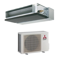
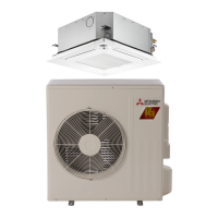
| Model | SUZ-KA24NAHZ |
| Refrigerant | R410A |
| Compressor Type | Inverter |
| Cooling Capacity (kW) | 7.03 kW |
| Cooling Capacity | 24, 000 BTU/hr |
| Voltage | 208/230 V |
| Phase | Single |
Lists the indoor unit service manual details and references.
Provides a general overview of safety precautions for servicing.
Emphasizes constant adherence to safety protocols during all operations.
Specific safety guidelines for handling R410A refrigerant and related components.
Important cautions to follow during the service process.
Guidance on refrigerant charging and necessary service tools.
Detailed precautions for refrigerant piping work, including pipe thickness and flare dimensions.
Explains the chargeless system for pre-charged refrigerant at shipment.
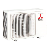
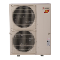
Detailed specifications for SUZ-KA24NAHZ and SUZ-KA30NAHZ models.
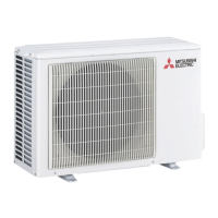
Detailed specifications for the SUZ-KA36NAHZ model.
Data on refilling refrigerant charge based on piping length.
Technical data for compressors, including winding resistance.
Graphs showing noise levels across frequency bands for different models.
Standard operation data for SVZ-KP24NA and SVZ-KP30NA models.
Standard operation data for the SVZ-KP36NA model.
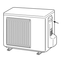
Dimensions, fire space, service space, and foundation bolt details for SUZ-KA24NAHZ.
Specific details regarding piping knock-out holes.
Dimensions, fire space, service space, and foundation bolt details for SUZ-KA30NAHZ/SUZ-KA36NAHZ.
Specific details regarding piping knock-out holes for additional models.
Electrical wiring diagram for the SUZ-KA24NAHZ model.
Electrical wiring diagrams for SUZ-KA30NAHZ and SUZ-KA36NAHZ models.
Specifications for indoor units powered by the outdoor unit, including wiring.
Warning regarding high voltage potential in A-control wiring.
Specifications for systems with separate power supplies for indoor and outdoor units.
Details on indoor-outdoor connecting cable types, sizes, and maximum lengths.
Diagram illustrating the refrigerant flow and components for SUZ-KA24NAHZ.
Diagrams showing refrigerant flow for SUZ-KA30NAHZ and SUZ-KA36NAHZ models.
Explanation of symbols used in the refrigerant system diagrams.
Step-by-step procedure for refrigerant collecting (pump down) before relocation or disposal.
Instructions for starting and finishing the test run operation.
Summary of actions for troubleshooting based on check codes and reoccurrence.
Points to check before test run, error information, history, and self-diagnosis.
Lists error codes and symptoms detected by the indoor unit.
Lists error codes and symptoms detected by outdoor units or communication.
Table detailing causes and actions for abnormalities detected upon power-on.
Details on specific errors like F5 (63H connector open) and EA/Eb/EC (wiring/startup issues).
Specific error codes and troubleshooting for U1 (high pressure) and U2 (high discharge temp).
Specific error codes and troubleshooting for U3, U4, U5, U6 related to thermistors and power module.
Specific error codes and troubleshooting for U7, U8, U9 related to superheat, fan, and voltage issues.
Specific error codes and troubleshooting for Ud, UE, UF, UH, UL, UP related to overheat, pressure, current, and compressor.
Specific error codes and troubleshooting for E0, E4, E1, E2 related to remote controller communication.
Specific error codes and troubleshooting for E3, E5, E6, E7, E8, E9 related to remote controller and unit communication.
Specific error codes and troubleshooting for Ed, EF, P8 related to communication and pipe temperature.
Specific error code PL related to abnormal refrigerant circuit and fan operation.
Troubleshooting steps for M-NET communication errors like A0, A2, A3, A6.
Troubleshooting steps for M-NET communication error A7 (No ACK signal).
Further troubleshooting for M-NET communication error A7 related to unit addresses and wiring.
Troubleshooting for M-NET communication error A8 (No ACK signal) and noise interference.
Guides for troubleshooting issues based on observed phenomena like remote controller display.
Troubleshooting for phenomena like remote controller display issues, capacity loss, and filter clogging.
Diagnostic flow for when "Please Wait" is continuously displayed on the remote controller.
Diagnostic flow for when the remote controller display is blank, checking power and wiring.
Diagnostic flow for blank remote controller display, checking LED status and refrigerant address.
Diagnostic flow for blank remote controller display, checking indoor unit LED2 and voltage.
Addresses common customer complaints like no display, unit not restarting, or error codes.
Explains meanings of display messages like "Please Wait", "Heat Standby", and "Heat Defrost".
Identifies and explains common sounds like gas escaping, cracking, buzzing, ticking, and water flow.
Addresses issues where fan speed or airflow direction does not match settings.
Explains why air may blow after HEAT operation stops.
Explains airflow direction changes during COOL and HEAT operations.
Addresses unit starting or stopping without remote controller input, including timers and central control.
Addresses mist expulsion from units and remote controller display/signal issues.
Provides resistance values for various thermistors at different temperatures.
Procedures for checking solenoid valve coil and compressor motor resistance.
Procedures for checking linear expansion valve and fan motor resistance.
Important notes regarding high voltage and connector handling during fan motor checks.
Steps for self-checking if the outdoor fan motor rotates correctly.
Charts detailing resistance values for low, medium, and high temperature thermistors.
Overview of LEV operation, pulse signals, and valve position control.
Details on LEV connection, pulse signals, and operational sounds.
Overview of LEV operation, pulse signals, and valve position control for KA30/36.
Details on LEV connection, pulse signals, and operational sounds for KA30/36.
Description of the main body and coil components of the LEV.
Step-by-step instructions for detaching and attaching the LEV coil.
Lists conditions for emergency operation and important cautions.
Step-by-step guide to perform emergency operation using switches.
Table showing operation data values used during emergency operation.
Diagram showing test points on the outdoor controller circuit board.
Diagram of the outdoor power circuit board for SUZ-KA24NAHZ.
Guidelines for checking the power module for shorts.
Diagrams of the outdoor power circuit board for SUZ-KA30NAHZ and SUZ-KA36NAHZ.
Guidelines for checking the power module for shorts for additional models.
Explains the functions and settings of various DIP switches.
Details on SW5, SW7, SW9, SW6, and connector CN31 functions.
How to enable low-level sound mode via external signal input.
How to reduce energy consumption using demand control via timer or switch.
Describes the LED indicators during normal operation.
Lists error codes indicated by LED blinking patterns for abnormal conditions.
Continues listing error codes and their inspection methods.
Details on LED1 and LED2 indicators for normal and abnormal states.
Explains displays for operation modes, error postponement, and blinking error codes.
Explains SW2 settings for displaying pipe temp, discharge temp, fan output, and compressor times.
Explains SW2 settings for compressor current, LEV pulse, and error history.
Explains SW2 settings for displaying operation mode during errors.
Explains SW2 settings for displaying error temperatures and histories.
Explains SW2 settings for thermostat ON time and test run elapsed time.
Explains SW2 settings for indoor temperatures and settings.
Explains SW2 settings for unit capacity and setting information.
Explains SW2 settings for discharge superheat, subcool, and LEV pulse.
Explains SW2 settings for U9 error history and input current.
Explains SW2 settings for DC bus voltage and capacity save modes.
Explains SW2 settings for error history and thermistor displays.
Explains SW2 settings for operation frequency and fan step on error.
Explains SW2 settings for LEV-C pulse and various indoor temperatures.
Explains SW2 settings for outdoor pipe, ambient, and heatsink temperatures.
Explains SW2 settings for discharge superheat and subcool on error.
Explains SW2 settings for thermo-on time and indoor pipe temperatures.
Explains the codes for controlling compressor operating frequency.
Explains SW2 settings for outdoor suction pipe temperature.
Explains SW2 settings for indoor pipe temperatures for multiple units.
Introduces the Smooth Maintenance feature and its benefits.
Explains how Smooth Maintenance reduces work and checks operation data.
Details on what information is displayed for easy maintenance checks.
Guides on checkpoints, temperature differences, and graphs for analyzing operation conditions.
How to set various unit functions using the remote controller.
Tables detailing available functions, their settings, and meanings.
Lists functions available based on unit number settings.
Examples of setting external static pressure for different models.
Instructions for selecting functions via the remote controller.
Guide on how to monitor operation data using the remote controller.
A comprehensive list of request codes for monitoring various operation data.
Continuation of the request code list for monitoring operation data.
Continuation of the request code list for monitoring operation data.
Continuation of the request code list for monitoring operation data.
Details for request code 0, covering operation state and relay outputs.
Details for request code 50, covering indoor unit control states.
Details for request code 51, covering outdoor unit control states.
Details for request code 52, covering compressor frequency control states.
Details for request code 53, covering fan control states.
Details for request code 54, covering actuator output states.
Details for request code 55, covering error content U9.
Details for request code 61, covering contact demand capacity.
Details for request code 62, covering external input states.
Details for request code 70, showing outdoor unit capacity settings.
Details for request code 71, showing outdoor unit settings like defrost mode.
Table mapping SW1-SW10 switch combinations to data display codes.
Details for request code 162, mapping display to model setting states.
Details for request code 163, mapping display to capacity setting states.
Details for request code 165, setting wireless pair numbers.
Step-by-step guide for disassembling the SUZ-KA24NAHZ unit.
Steps for removing the service panel and top panel.
Steps for removing the fan motor (MF1).
Steps for removing the electrical parts box.
Steps for removing liquid, 2-phase pipe, and ambient thermistors.
Steps for removing discharge and compressor surface thermistors.
Steps for removing the 4-way valve coil and LEV coils.
Steps for removing the 4-way valve assembly.
Steps for removing the linear expansion valve.
Steps for removing the high pressure switch.
Steps for removing the high pressure switch (continued).
Steps for removing the reactor (DCL) component.
Steps for removing the compressor (MC).
Steps for removing the power receiver.
Steps for removing the base heater and its support.
Step-by-step guide for disassembling the SUZ-KA30NAHZ/SUZ-KA36NAHZ unit.
Steps for removing service and top panels for these models.
Steps for removing fan motors for these models.
Steps for removing the electrical parts box for these models.
Steps for removing 2-phase pipe and ambient thermistors.
Steps for removing the discharge thermistor.
Steps for removing liquid, suction, and compressor surface thermistors.
Steps for removing 4-way valve and LEV coils.
Steps for removing the 4-way valve assembly.
Steps for removing the linear expansion valve.
Steps for removing the high pressure switch.
Steps for removing the high pressure switch (continued).
Steps for removing the reactor (DCL).
Steps for removing the compressor.
Steps for removing the power receiver.
Steps for removing the base heater.
Overview of the remote controller interface, functions, and buttons.
Explanation of the differences between Full and Basic display modes.
Explanation of various icons and settings displayed on the remote controller.
Overview of the main menu structure and navigation.
Details on Operation, Timer, and Energy Saving submenus.
Details on the Initial Setting menu options.
Detailed explanation of Operation settings like vane, high power, and comfort.
Detailed explanation of Timer and Energy Saving settings.
Detailed explanation of Basic Setting, Clock, and Administrator password.
Details for Display and Operation settings like Auto mode and Setback mode.
Details for Maintenance and Service menus like Error Information and Test Run.
Details for Settings, Check, and Other menus like Error History and Smooth Maintenance.
Diagram of the controller interface and explanation of buttons.
Operating tips and precautions for using the remote controller.
Diagram of the controller interface and explanation of buttons.
Explanation of display elements like operation mode, temperature, and fan speed.
Explanation of settings for vane, fan speed, and 3D i-See sensor.
Steps to check error status, stop operation, and reset errors.
How to view error information from the Maintenance menu when no active errors are present.
Instructions for accessing the Service menu, including password entry and navigation.
Information on saving settings and the types of menus available based on indoor units.
Step-by-step guide for performing a test run on the PAR-40MAA model.
Details on operating the unit during test run and checking auto vane function.
Steps for performing a test run on the PAR-SL97A-E model.
Steps for performing a test run on the PAR-SL100A-E model.
Step-by-step guide for setting functions on the PAR-40MAA remote controller.
Notes regarding indoor unit fan operation during settings and general function setting advice.
Flow chart and instructions for selecting functions using the PAR-SL97A-E controller.
Operating instructions and important notes for setting functions.
Step-by-step guide for selecting functions using the PAR-SL100A-E controller.
Reminder to record initial settings and notes on function availability.
Steps to navigate and view recorded error history.
Procedure for deleting error history records after confirmation.
Steps for performing self-diagnosis and checking unit/error information.
Steps to reset error history, including confirmation and error messages.
Procedure for diagnosing malfunctions using the PAR-SL97A-E controller.
Procedure for diagnosing malfunctions using the PAR-SL100A-E controller.
How to check the remote controller display and diagnose issues.
How to interpret check results and handle potential problems like noise or faulty controllers.
Steps to access Smooth Maintenance and set items like reference address and stable mode.
How to view operation data such as compressor status and temperatures.
Explanation of refrigerant addresses for single and multi-system configurations.
Procedure for setting refrigerant address and requesting operation data.