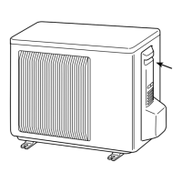
Do you have a question about the Mitsubishi Electric SUZ-KA25VA2 and is the answer not in the manual?
| Category | Air Conditioner |
|---|---|
| Model | SUZ-KA25VA2 |
| Type | Outdoor Unit |
| Cooling Capacity | 2.5 kW |
| Heating Capacity | 3.2 kW |
| Power Supply | 220-240 V, 50 Hz |
| Refrigerant | R32 |
| Outdoor Unit Dimensions (HxWxD) | 550 x 800 x 285 mm |
| Noise Level (Outdoor) | 49 dB(A) |
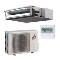
Lists combinations of indoor and outdoor units for heat pump systems.
Details on R410A refrigerant properties, handling, and comparison with R22.
Lists dedicated and substitutable tools required for R410A refrigerant systems.
Specifications for refrigerant pipes, oil, air purge, and charging procedures.
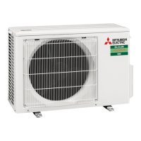
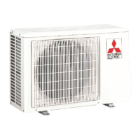
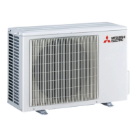
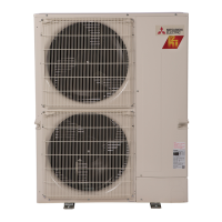
Diagrams identifying external parts of SUZ-KA outdoor units.
Detailed electrical, fan, compressor, and sound level specs for SUZ-KA models.
Octave band sound pressure level data for cooling/heating for different models.
Diagrams showing external dimensions and required installation space for SUZ-KA25/35VA2.TH.
Diagrams showing external dimensions and required installation space for SUZ-KA50/60VA2.TH.
Diagrams showing external dimensions and required installation space for SUZ-KA71VA2.TH.
Electrical wiring diagram for SUZ-KA25/35VA2.TH outdoor units.
Electrical wiring diagram for SUZ-KA50VA2.TH outdoor unit.
Electrical wiring diagram for SUZ-KA60VA2.TH outdoor unit.
Electrical wiring diagram for SUZ-KA71VA2.TH outdoor unit.
Diagram illustrating refrigerant flow and components for SUZ-KA25/35VA2.TH.
Diagram illustrating refrigerant flow and components for SUZ-KA50/60VA2.TH.
Diagram illustrating refrigerant flow and components for SUZ-KA71VA2.TH.
Timing and interlocking logic for the outdoor fan motor operation with the compressor.
Control logic for the R.V. coil in cooling and heating modes.
Table mapping sensors to actuators for protection and control purposes.
How to change the defrost finish temperature by modifying the JS wire.
Precautions to take before and during troubleshooting procedures.
Procedures for recalling failure modes and interpreting indicator lights.
Table of LED indications and corresponding failure modes for outdoor units.
Step-by-step diagnostic flows for key electrical and mechanical components.
Procedures to check for miswiring and serial signal errors between units.
Steps to identify and mitigate electromagnetic noise interference.
Step-by-step guide for removing the outer cabinet panels of the outdoor units.
Instructions for removing the inverter assembly and related electronic boards.
Procedures for removing the R.V. coil, thermistors, and fan motor.
Steps for safely removing the compressor, 4-way valve, and reactor.




 Loading...