EasyManua.ls Logo

Mitsubishi Electric SUZ-KA25VA2 User Manual

Mitsubishi Electric SUZ-KA25VA2
74 pages
To Next Page IconTo Next Page
Page #1 background imageLoading...
Page #1 background image
TECHNICAL & SERVICE MANUAL
No.OCH472
REVISED EDITION-A
SPLIT-TYPE, HEAT PUMP AIR CONDITIONERS
R410A
Outdoor unit
[Model names]
[Service Ref.]
SUZ-KA25VA2 SUZ-KA25VA2.TH
SUZ-KA35VA2 SUZ-KA35VA2.TH
SUZ-KA50VA2 SUZ-KA50VA2.TH
SUZ-KA60VA2 SUZ-KA60VA2.TH
SUZ-KA71VA2 SUZ-KA71VA2.TH
CONTENTS
1.
COMBINATION OF INDOOR AND OUTDOOR UNITS
.......
2
2. TECHNICAL CHANGES
....................................
3
3. PART NAMES AND FUNCTIONS
......................
6
4. SPECIFICATION
.................................................
7
5. NOISE CRITERIA CURVES
...............................
9
6. OUTLINES AND DIMENSIONS
........................
10
7. WIRING DIAGRAM
...........................................
13
8. REFRIGERANT SYSTEM DIAGRAM
..............
17
9. ACTUATOR CONTROL
....................................
21
10. SERVICE FUNCTIONS
.....................................
22
11. TROUBLESHOOTING
......................................
22
12. DISASSEMBLY INSTRUCTIONS
.....................
63
Indication of
model name
NOTE:
This service manual describes technical data of the
outdoor units.
RoHS compliant products have <G> mark on the spec
name plate.
For servicing of RoHS compliant products, refer to the
RoHS Parts List.
HFC
utilized
R410A
SUZ-KA25VA2.TH
SUZ-KA35VA2.TH
September 2011
PARTS CATALOG (OCB472)
Revision:
• Errors in "11.
TROUBLESHOOTING"
have been corrected in
REVISED EDITION-A.
• Some descriptions have
been modified.
Please void OCH472.
Question and Answer IconNeed help?

Do you have a question about the Mitsubishi Electric SUZ-KA25VA2 and is the answer not in the manual?
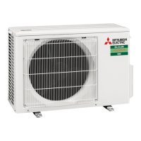
Mitsubishi Electric SUZ-KA25VA2 Specifications

General IconGeneral
CategoryAir Conditioner
ModelSUZ-KA25VA2
TypeOutdoor Unit
Cooling Capacity2.5 kW
Heating Capacity3.2 kW
Power Supply220-240 V, 50 Hz
RefrigerantR32
Outdoor Unit Dimensions (HxWxD)550 x 800 x 285 mm
Noise Level (Outdoor)49 dB(A)

Summary

Indoor and Outdoor Unit Combinations

1-1. Indoor Unit Service Manual Combinations

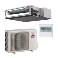
Lists combinations of indoor and outdoor units for heat pump systems.

Technical Changes and R410A Introduction

R410A Refrigerant Properties and Comparison

Details on R410A refrigerant properties, handling, and comparison with R22.

Tools for R410A Refrigerant Systems

Lists dedicated and substitutable tools required for R410A refrigerant systems.

R410A Piping, Oil, and Charging Procedures

Specifications for refrigerant pipes, oil, air purge, and charging procedures.

Part Names and Functions Overview

Outdoor Unit Component Identification

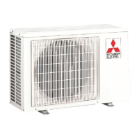
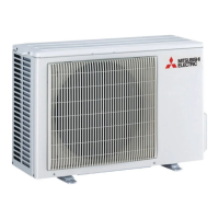
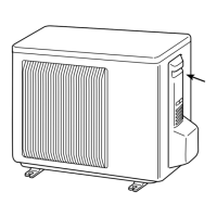
Diagrams identifying external parts of SUZ-KA outdoor units.

Outdoor Unit Specifications

Performance Specifications Table

Detailed electrical, fan, compressor, and sound level specs for SUZ-KA models.

Noise Criteria Curves

Noise Level Data by Frequency Band

Octave band sound pressure level data for cooling/heating for different models.

Outline and Dimensions

SUZ-KA25/35VA2.TH Dimensions and Clearance

Diagrams showing external dimensions and required installation space for SUZ-KA25/35VA2.TH.

SUZ-KA50/60VA2.TH Dimensions and Clearance

Diagrams showing external dimensions and required installation space for SUZ-KA50/60VA2.TH.

SUZ-KA71VA2.TH Dimensions and Clearance

Diagrams showing external dimensions and required installation space for SUZ-KA71VA2.TH.

Wiring Diagrams

Wiring Diagram for SUZ-KA25/35VA2.TH

Electrical wiring diagram for SUZ-KA25/35VA2.TH outdoor units.

Wiring Diagram for SUZ-KA50VA2.TH

Electrical wiring diagram for SUZ-KA50VA2.TH outdoor unit.

Wiring Diagram for SUZ-KA60VA2.TH

Electrical wiring diagram for SUZ-KA60VA2.TH outdoor unit.

Wiring Diagram for SUZ-KA71VA2.TH

Electrical wiring diagram for SUZ-KA71VA2.TH outdoor unit.

Refrigerant System Diagrams

Refrigerant Diagram for SUZ-KA25/35VA2.TH

Diagram illustrating refrigerant flow and components for SUZ-KA25/35VA2.TH.

Refrigerant Diagram for SUZ-KA50/60VA2.TH

Diagram illustrating refrigerant flow and components for SUZ-KA50/60VA2.TH.

Refrigerant Diagram for SUZ-KA71VA2.TH

Diagram illustrating refrigerant flow and components for SUZ-KA71VA2.TH.

Actuator Control Logic

Outdoor Fan Motor Control Logic

Timing and interlocking logic for the outdoor fan motor operation with the compressor.

Reversing Valve (R.V.) Coil Control

Control logic for the R.V. coil in cooling and heating modes.

Sensor and Actuator Interaction Table

Table mapping sensors to actuators for protection and control purposes.

Service Functions

Defrost Setting Adjustment Procedure

How to change the defrost finish temperature by modifying the JS wire.

Troubleshooting Guide

General Troubleshooting Cautions

Precautions to take before and during troubleshooting procedures.

Failure Mode Recall Function Procedure

Procedures for recalling failure modes and interpreting indicator lights.

Outdoor Unit Failure Indications (LEDs)

Table of LED indications and corresponding failure modes for outdoor units.

Component Diagnostic Troubleshooting Flows

Step-by-step diagnostic flows for key electrical and mechanical components.

Wiring and Serial Signal Error Checks

Procedures to check for miswiring and serial signal errors between units.

Electromagnetic Noise Troubleshooting Steps

Steps to identify and mitigate electromagnetic noise interference.

Disassembly Instructions

Cabinet and Panel Removal Procedures

Step-by-step guide for removing the outer cabinet panels of the outdoor units.

Inverter Assembly and Board Removal Steps

Instructions for removing the inverter assembly and related electronic boards.

Component Removal: R.V. Coil, Thermistors, Fan Motor

Procedures for removing the R.V. coil, thermistors, and fan motor.

Compressor, 4-Way Valve, and Reactor Removal

Steps for safely removing the compressor, 4-way valve, and reactor.

Related product manuals