EasyManua.ls Logo

Mitsubishi Electric SUZ-KA71VA2 User Manual

Mitsubishi Electric SUZ-KA71VA2
74 pages
To Next Page IconTo Next Page
Page #1 background imageLoading...
Page #1 background image
TECHNICAL & SERVICE MANUAL
No.OCH472
SPLIT-TYPE, HEAT PUMP AIR CONDITIONERS
R410A
Outdoor unit
[model names]
[Service Ref.]
SUZ-KA25VA2 SUZ-KA25VA2.TH
SUZ-KA35VA2 SUZ-KA35VA2.TH
SUZ-KA50VA2 SUZ-KA50VA2.TH
SUZ-KA60VA2 SUZ-KA60VA2.TH
SUZ-KA71VA2 SUZ-KA71VA2.TH
CONTENTS
1.
COMBINATION OF INDOOR AND OUTDOOR UNITS
.......
2
2. TECHNICAL CHANGES
....................................
3
3. PART NAMES AND FUNCTIONS
......................
6
4. SPECIFICATION
.................................................
7
5. NOISE CRITERIA CURVES
...............................
9
6. OUTLINES AND DIMENSIONS
........................
10
7. WIRING DIAGRAM
...........................................
13
8. REFRIGERANT SYSTEM DIAGRAM
..............
17
9. ACTUATOR CONTROL
....................................
21
10. SERVICE FUNCTIONS
.....................................
22
11. TROUBLESHOOTING
......................................
22
12. DISASSEMBLY INSTRUCTIONS
.....................
63
Indication of
model name
NOTE:
This service manual describes technical data of the
outdoor units.
RoHS compliant products have <G> mark on the spec
name plate.
For servicing of RoHS compliant products, refer to the
RoHS Parts List.
HFC
utilized
R410A
SUZ-KA25VA2.TH
SUZ-KA35VA2.TH
May 2010
PARTS CATALOG (OCB472)
Question and Answer IconNeed help?

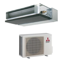
Do you have a question about the Mitsubishi Electric SUZ-KA71VA2 and is the answer not in the manual?

Mitsubishi Electric SUZ-KA71VA2 Specifications

General IconGeneral
CategoryAir Conditioner
Cooling Capacity7.1 kW
Heating Capacity8.0 kW
Power Supply220-240V, 50Hz
RefrigerantR32
Sound Power Level Heating66 dB(A)
Outdoor Unit Dimensions (H x W x D)880 x 840 x 330 mm
Outdoor Unit Weight55 kg
Seasonal Energy Efficiency Ratio (SEER)6.1
Sound Power Level Cooling65 dB

Summary

1 COMBINATION OF INDOOR AND OUTDOOR UNITS

1-1. INDOOR UNIT SERVICE MANUAL

Details on indoor unit service manual for unit combinations.

2 TECHNICAL CHANGES

1. Tools dedicated for the air conditioner with R410A refrigerant

Required tools and their specifications for R410A refrigerant.

2. Refrigerant piping

Specifications for refrigerant pipes used with R410A.

3 PART NAMES AND FUNCTIONS

4 SPECIFICATION

5 NOISE CRITERIA CURVES

6 OUTLINES AND DIMENSIONS

7 WIRING DIAGRAM

8 REFRIGERANT SYSTEM DIAGRAM

9 ACTUATOR CONTROL

9-1. Outdoor fan motor control

Control logic for the outdoor fan motor operation.

9-2. R.V. coil control

Operation modes for the reversing valve coil.

9-3. Relation between main sensor and actuator

Correlation between system sensors and actuators.

10 SERVICE FUNCTIONS

CHANGE IN DEFROST SETTING

Adjusting defrost finish temperature via jumper wire.

11 TROUBLESHOOTING

11-1. Cautions on troubleshooting

Important precautions and checks before troubleshooting.

11-2. Failure mode recall function

Procedure to recall and diagnose past unit failures.

11-3. Trouble shooting check table

Table listing symptoms, LED indications, and troubleshooting steps.

11-4. Trouble criterion of main parts (1)

Criteria for checking main components like thermistors and compressor.

11-4. Trouble criterion of main parts (2)

Criteria for checking main components like fan motor and R.V. coil.

11-5. Troubleshooting flow

Step-by-step guides for diagnosing specific issues.

11-6. Test point diagram and voltage

Diagrams and voltage references for electrical components.

12 DISASSEMBLY INSTRUCTIONS

Related product manuals