EasyManua.ls Logo

Mitsubishi Electric SUZ-KA35VAH User Manual

Mitsubishi Electric SUZ-KA35VAH
130 pages
To Next Page IconTo Next Page
Page #1 background imageLoading...
Page #1 background image
TECHNICAL & SERVICE MANUAL
No.OC322
SPLIT-TYPE, HEAT PUMP AIR CONDITIONERS
R410A
Outdoor unit
[model names]
[Service Ref.]
SUZ-KA25VA SUZ-KA25VA.TH SUZ-KA25VAR1.TH
SUZ-KA35VA SUZ-KA35VA.TH SUZ-KA35VAR1.TH
SUZ-KA25VAH SUZ-KA25VAH.TH
SUZ-KA25VAHR1.TH
SUZ-KA35VAH SUZ-KA35VAH.TH
SUZ-KA35VAHR1.TH
SUZ-KA50VA SUZ-KA50VA.TH
SUZ-KA50VA1.TH
SUZ-KA50VAR2.TH
SUZ-KA60VA SUZ-KA60VA.TH
SUZ-KA60VA1.TH
SUZ-KA60VAR2.TH
SUZ-KA71VA SUZ-KA71VA.TH
SUZ-KA71VA1.TH
CONTENTS
1.
COMBINATION OF INDOOR AND OUTDOOR UNITS
.......
2
2. TECHNICAL CHANGES
....................................
3
3. PART NAMES AND FUNCTIONS
......................
7
4. SPECIFICATION
.................................................
8
5. NOISE CRITERIA CURVES
..............................
12
6. OUTLINES AND DIMENSIONS
........................
13
7. WIRING DIAGRAM
...........................................
15
8. REFRIGERANT SYSTEM DIAGRAM
..............
23
9. PERFORMANCE CURVES
..............................
29
10. ACTUATOR CONTROL
....................................
57
11. SERVICE FUNCTIONS
.....................................
58
12. TROUBLESHOOTING
......................................
58
13. DISASSEMBLY INSTRUCTIONS
...................
103
14. PARTS LIST
....................................................
113
15. RoHS PARTS LIST
.........................................
119
Indication of
model name
NOTE:
This service manual describes technical data of the
outdoor units.
RoHS compliant products have <G> mark on the spec
name plate.
For servicing of RoHS compliant products, refer to the
RoHS Parts List.
HFC
utilized
R410A
SUZ-KA25VA(H).TH SUZ-KA25VA(H)R1.TH
SUZ-KA35VA(H).TH SUZ-KA35VA(H)R1.TH
April 2009
REVISED EDITION-E
Revision:
SUZ-KA25/35VA(H)R1.TH
are added in REVISED
EDITION-E.
• Some descriptions
have been modified.
• Please void OC322
REVISED EDITION-D.

Other manuals for Mitsubishi Electric SUZ-KA35VAH

Question and Answer IconNeed help?

Do you have a question about the Mitsubishi Electric SUZ-KA35VAH and is the answer not in the manual?
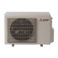
Mitsubishi Electric SUZ-KA35VAH Specifications

General IconGeneral
CategoryAir Conditioner
BrandMitsubishi Electric
ModelSUZ-KA35VAH
TypeOutdoor Unit
Cooling Capacity3.5 kW
Heating Capacity4.0 kW
Seasonal Energy Efficiency Ratio (SEER)6.1
Power Supply220-240 V, 50 Hz
RefrigerantR32
Outdoor Unit Dimensions (W x H x D)800 x 550 x 285 mm

Summary

Combination of Indoor and Outdoor Units

Technical Changes

Part Names and Functions

Specification

Noise Criteria Curves

Outlines and Dimensions

Wiring Diagram

Refrigerant System Diagram

Performance Curves

How to Measure Indoor Air Wet-bulb/Dry-bulb Temperature Difference

Explains how to measure indoor air wet/dry-bulb temperature difference for performance analysis.

Actuator Control

Outdoor Fan Motor Control

Details the ON/OFF control of the outdoor fan motor in relation to the compressor.

R.V. Coil Control

Explains the control states (ON/OFF) for heating, cooling, and dry modes of the R.V. coil.

Relation Between Main Sensor and Actuator

Maps sensors to actuators (compressor, LEV, fan motors, etc.) for different model series.

Service Functions

Change in Defrost Setting

Explains how to change defrost settings via jumper wire modification.

Troubleshooting

Cautions on Troubleshooting

Provides essential safety precautions before starting any troubleshooting procedures.

Failure Mode Recall Function

Explains how to recall and display the latest failure details using the failure mode recall function.

Flow Chart of Indoor/Outdoor Unit Failure Mode Recall Function

Provides a step-by-step flowchart for recalling failure modes via wireless remote controller.

Failure Mode Table (Wireless/Wired Remote Controller)

Lists failure codes, symptoms, and corresponding checks for both wireless and wired remote controllers.

Outdoor Unit Failure Mode Table

Details outdoor unit failure modes based on LED indications, their causes, and check points.

Troubleshooting Check Table

Provides a table with symptoms, LED indications, detection methods, and corresponding checks for specific models.

Trouble Criterion of Main Parts (1)

Lists main parts, their check methods, and criteria for identifying defects.

Trouble Criterion of Main Parts (2)

Continues listing main parts, their check methods, and criteria for identifying defects.

Troubleshooting Flow

Provides troubleshooting flowcharts for specific issues like inverter/compressor checks.

Test Point Diagram and Voltage

Shows test points and voltage readings on the Inverter P.C. board with relevant diagrams.

Disassembly Instructions

1. Removing the Cabinet

Details the steps for removing the outdoor unit cabinet, including service panel and top panel.

2. Removing the Inverter Assembly, Inverter P.C. Board and Power P.C. Board

Provides steps for removing the inverter and power P.C. boards, including disconnecting wires and connectors.

3. Removing R.V. Coil

Details the procedure for removing the R.V. coil after disconnecting power and other components.

4. Removing the Discharge Temperature Thermistor and Defrost Thermistor

Explains how to remove specific thermistors by pulling them from their holders.

5. Removing Outdoor Fan Motor

Outlines the steps to remove the outdoor fan motor, including propeller and nut.

6. Removing the Compressor and 4-way Valve

Details the process for removing the compressor and 4-way valve, including gas recovery.

Parts List (Non-RoHS Compliant)

14-1. Outdoor Unit Electrical Parts

Lists electrical components of the outdoor unit with part numbers and quantities.

14-2. Outdoor Unit Structural Parts and Functional Parts

Lists structural and functional parts of the outdoor unit with part numbers and quantities.

14-3. Outdoor Unit Structural Parts, Electrical Parts and Functional Parts

Lists structural, electrical, and functional parts of the outdoor unit for specific models.

14-4. Drain Socket

Lists the part number and quantity for the drain socket.

14-5. Accessory

Lists accessory parts like drain socket and drain cap with part numbers and quantities.

RoHS Parts List

15-1. Outdoor Unit Electrical Parts

Lists RoHS compliant electrical components of the outdoor unit with part numbers.

15-2. Outdoor Unit Structural Parts and Functional Parts

Lists RoHS compliant structural and functional parts of the outdoor unit with part numbers.

15-3. Outdoor Unit Electrical Parts

Lists RoHS compliant electrical parts for specific outdoor unit models with part numbers.

15-4. Outdoor Unit Structural Parts and Functional Parts

Lists RoHS compliant structural and functional parts for specific outdoor unit models with part numbers.

15-5. Outdoor Unit Structural Parts, Electrical Parts and Functional Parts

Lists RoHS compliant structural, electrical, and functional parts for specific outdoor unit models with part numbers.

Related product manuals