SERVICE MANUAL
SPLIT-TYPE, HEAT PUMP AIR CONDITIONERS
HFC
utilized
R410A
R410A
Note:
This service manual describes
service data of the outdoor units
only.
PARTS CATALOG (OCB699)
No. OCH699
REVISED EDITION-A
June 2021
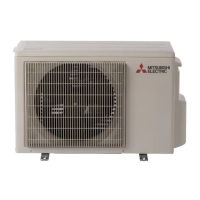
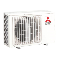
Outdoor unit
[Model Name]
SUZ-KA09NA2
SUZ-KA09NAH2
SUZ-KA12NA2
SUZ-KA12NAH2
SUZ-KA15NA2
SUZ-KA15NAH2
[Service Ref.]
SUZ-KA09NA2.MX
SUZ-KA09NAH2.MX
SUZ-KA12NA2.MX
SUZ-KA12NAH2.MX
SUZ-KA15NA2.MX
SUZ-KA15NAH2.MX
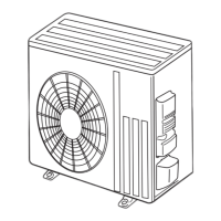
SUZ-KA09NA(H)2.MX
Air outlet
Drain outlet
Piping
Drain hose
Air inlet
(back and side)
CONTENTS
1. COMBINATION OF INDOOR AND
OUTDOOR UNITS ······························2
2. PART NAMES AND FUNCTIONS ·········· 2
3. SPECIFICATION ································3
4. OUTLINES AND DIMENSIONS ·············4
5. WIRING DIAGRAM ·····························5
6. REFRIGERANT SYSTEM DIAGRAM ·····9
7. DATA ·············································· 10
8. ACTUATOR CONTROL ····················· 12
9. SERVICE FUNCTION ························ 13
10. TROUBLESHOOTING ······················· 13
11. FUNCTION SETTING ························ 29
12. DISASSEMBLY INSTRUCTIONS ········· 32
Revision:
Some descriptions have
been modified in REVISED
EDITION-A.
OCH699 is void.
MITSUBISHI
ELECTRIC