EasyManua.ls Logo

Mitsubishi Electric SUZ-KA71VA4 User Manual

Mitsubishi Electric SUZ-KA71VA4
46 pages
To Next Page IconTo Next Page
Page #1 background imageLoading...
Page #1 background image
TECHNICAL & SERVICE MANUAL
No.OCH545
SPLIT-TYPE, HEAT PUMP AIR CONDITIONERS
R410A
Outdoor unit
[Model Name]
[Service Ref.]
SUZ-KA25VA4 SUZ-KA25VA4.TH
SUZ-KA35VA4 SUZ-KA35VA4.TH
SUZ-KA50VA4 SUZ-KA50VA4.TH
SUZ-KA60VA4 SUZ-KA60VA4.TH
SUZ-KA71VA4 SUZ-KA71VA4.TH
CONTENTS
1.
COMBINATION OF INDOOR AND OUTDOOR UNITS
.....
2
2. TECHNICAL CHANGES
...................................
3
3. PARTS NAMES AND FUNCTIONS
..................
7
4. SPECIFICATION
................................................
8
5. NOISE CRITERIA CURVES
............................
10
6. OUTLINES AND DIMENSIONS
.......................
11
7. WIRING DIAGRAM
..........................................
13
8. REFRIGERANT SYSTEM DIAGRAM
.............
16
9. ACTUATOR CONTROL
...................................
19
10. SERVICE FUNCTIONS
....................................
20
11. TROUBLESHOOTING
.....................................
20
12. DISASSEMBLY INSTRUCTIONS
....................
36
Indication of
model name
Note:
This service manual
describes technical data of
the outdoor units.
HFC
utilized
R410A
SUZ-KA25VA4.TH
SUZ-KA35VA4.TH
August 2013
PARTS CATALOG (OCB545)
Question and Answer IconNeed help?

Do you have a question about the Mitsubishi Electric SUZ-KA71VA4 and is the answer not in the manual?
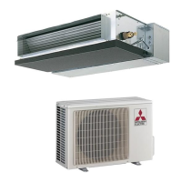
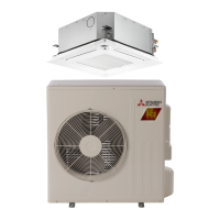
Mitsubishi Electric SUZ-KA71VA4 Specifications

General IconGeneral
BrandMitsubishi Electric
ModelSUZ-KA71VA4
CategoryAir Conditioner
LanguageEnglish

Summary

1. COMBINATION OF INDOOR AND OUTDOOR UNITS

2. TECHNICAL CHANGES

INFORMATION FOR THE AIR CONDITIONER WITH R410A REFRIGERANT

Provides information on R410A refrigerant for air conditioners.

1. Tools dedicated for the air conditioner with R410A refrigerant

Lists and describes tools required for R410A refrigerant systems.

2. Refrigerant piping

Details specifications for refrigerant piping, including diameter, thickness, and insulation.

3. Refrigerant oil

Instructions for applying refrigerant oil to flare and union seat surfaces.

4. Air purge

Guidelines for air purging using a vacuum pump for environmental protection.

5. Additional charge

Procedures for additional refrigerant charging, emphasizing liquid phase charging.

6. Pumping Down

Step-by-step procedure for pumping down the air conditioner system.

3. PARTS NAMES AND FUNCTIONS

4. SPECIFICATION

Specifications and rating conditions of main electric parts

Lists specifications and ratings for key electrical components.

5. NOISE CRITERIA CURVES

6. OUTLINES AND DIMENSIONS

7. WIRING DIAGRAM

8. REFRIGERANT SYSTEM DIAGRAM

MAX. REFRIGERANT PIPING LENGTH

ADDITIONAL REFRIGERANT CHARGE (R410A: g)

Details additional refrigerant charge amounts based on piping length.

9. ACTUATOR CONTROL

9-1. OUTDOOR FAN MOTOR CONTROL

Explains the control logic for the outdoor fan motor operation.

9-2. R.V. COIL CONTROL

Describes the control sequences for the reversing valve (R.V.) coil in cooling and heating.

9-3. RELATION BETWEEN MAIN SENSOR AND ACTUATOR

Shows the relationship between various sensors and actuators in the system.

10. SERVICE FUNCTIONS

CHANGE IN DEFROST SETTING

Instructions on how to change the defrost finish temperature setting.

11. TROUBLESHOOTING

11-1. CAUTIONS ON TROUBLESHOOTING

Important safety precautions and general checks before starting troubleshooting.

11-2. TROUBLE SHOOTING CHECK TABLE

A table listing symptoms, check codes, conditions, and remedies for troubleshooting.

11-3. HOW TO PROCEED "SELF-DIAGNOSIS"

Guide on how to use the self-diagnosis function to recall failures.

11-3-1. Self-diagnosis <PAR-30MAA> <PAR-31MAA>

Steps for performing self-diagnosis using specific remote controllers.

11-3-2. Remote controller check <PAR-30MAA> <PAR-31MAA>

Procedure to diagnose the remote controller using its built-in function.

11-3-3. Self-diagnosis <PAR-21MAA>

Self-diagnosis procedure for the PAR-21MAA remote controller.

11-3-4. Self-Diagnosis During Maintenance or Service <PAR-21MAA>

Recalling error code history during maintenance for PAR-21MAA controller.

11-3-5. Remote controller check <PAR-21MAA>

Diagnosing the remote controller when the unit cannot be operated.

11-3-6. Self-diagnosis <Wireless remote controller>

Self-diagnosis procedure for wireless remote controllers in case of trouble.

Check codes

Details error codes detected by indoor and outdoor units with symptoms and remarks.

11-4. TROUBLE CRITERION OF MAIN PARTS

11-5. TROUBLESHOOTING FLOW

How to check inverter/compressor

Step-by-step guide to check the inverter and compressor for issues.

Check of compressor

Procedure to check the compressor's normal operation and continuity.

D Check of compressor winding

Method to measure compressor winding resistance to detect shorts or opens.

E Check of compressor operation time

Procedure to measure the time until the inverter stops due to overcurrent.

F Check of outdoor thermistors

Steps to check the resistance of outdoor unit thermistors.

G Check of R.V. coil

Steps to check the resistance of the R.V. coil and related voltages.

H Check of outdoor fan motor

Procedure to check the resistance and voltage of the outdoor fan motor.

Check of LEV

Checks for LEV coil operation, sound, vibration, and resistance.

J Check of inverter P.C. board

Steps to check the inverter P.C. board, including fuse, connectors, and LED indication.

K Electromagnetic noise enters into TV sets or radios

11-6. TEST POINT DIAGRAM AND VOLTAGE

11-6-1. Inverter P.C. board

Test point diagram and voltage checks for the inverter P.C. board.

11-6-2. Inverter P.C. board

Test point diagram and voltage checks for the inverter P.C. board.

12. DISASSEMBLY INSTRUCTIONS

1. Removing the cabinet

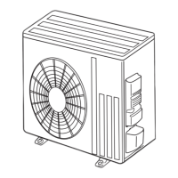
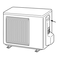
Step-by-step instructions for removing the outdoor unit cabinet.

2. Removing the inverter assembly, inverter P.C. board

Procedure to remove the inverter assembly and P.C. board.

3. Removing R.V. coil

Steps to disconnect and remove the R.V. coil.

5. Removing outdoor fan motor

Procedure to remove the outdoor fan motor and its components.

6. Removing the compressor and 4-way valve

Steps to remove the compressor and 4-way valve.

Related product manuals