EasyManua.ls Logo

Mitsubishi Electric SUZ-KA18NAHZ User Manual

Mitsubishi Electric SUZ-KA18NAHZ
38 pages
To Next Page IconTo Next Page
Page #1 background imageLoading...
Page #1 background image
SERVICE MANUAL
R410A
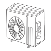
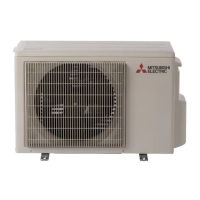
Outdoor unit
[Model Name]
SUZ-KA09NAHZ
SUZ-KA12NAHZ
SUZ-KA15NAHZ
SUZ-KA18NAHZ
[Service Ref.]
SUZ-KA09NAHZ.TH
SUZ-KA12NAHZ.TH
SUZ-KA15NAHZ.TH
SUZ-KA18NAHZ.TH
PARTS CATALOG (OCB709)
CONTENTS
1.
COMBINATION OF INDOOR AND OUTDOOR UNITS
...
2
2. PART NAMES AND FUNCTIONS
......................
2
3. SPECIFICATION
.................................................
3
4. OUTLINES AND DIMENSIONS
..........................
4
5. WIRING DIAGRAM
............................................
5
6. REFRIGERANT SYSTEM DIAGRAM
................
7
7. DATA
...................................................................
9
8. ACTUATOR CONTROL
.....................................
14
9. SERVICE FUNCTIONS
......................................
15
10. TROUBLESHOOTING
.......................................
15
11. FUNCTION SETTING
........................................
32
12. DISASSEMBLY INSTRUCTIONS
......................
35
Note:
This manual describes
service data of the outdoor
units only.
No. OCH709
REVISED EDITION-A
December 2019
SPLIT-TYPE, AIR CONDITIONERS
SUZ-KA09NAHZ.TH
OCH709 is void.
Revision:
3.SPECIFICATION has
been revised in REVISED
EDITION-A.

Questions and Answers:

Mitsubishi Electric SUZ-KA18NAHZ Specifications

General IconGeneral
BrandMitsubishi Electric
ModelSUZ-KA18NAHZ
CategoryAir Conditioner
LanguageEnglish

Summary

Specification

Data

Actuator Control

Service Functions

Troubleshooting

10-1. Cautions on Troubleshooting

Provides essential safety precautions and general checks before performing troubleshooting procedures.

10-2. Troubleshooting Check Table

Lists LED indications, check codes, symptoms, conditions, and remedies for troubleshooting.

10-3. How to Proceed "Self-Diagnosis"

Guides users on using the remote controller's self-diagnosis function to identify errors.

10-4. Trouble Criterion of Main Parts

Details resistance and voltage criteria for checking key components like thermistors, motors, and coils.

10-5. Troubleshooting Flow

Outlines step-by-step diagnostic procedures for checking the inverter and compressor.

10-6. Test Point Diagram and Voltage

Provides detailed diagrams of the inverter P.C. board with test points and voltage specifications.

Function Setting

Disassembly Instructions

Related product manuals