EasyManua.ls Logo

Mitsubishi Electric SUZ-KA50VA User Manual

Mitsubishi Electric SUZ-KA50VA
118 pages
To Next Page IconTo Next Page
Page #1 background imageLoading...
Page #1 background image
600o600
CEILING
CASSETTE
CEILING
CONCEALED
OUTDOOR
UNIT
B.1 600 o 600 CEILING CASETTE (SLZ) ....................................................B-3
Combination Table .........................................................................................B-2
SLZ-KA25VA
SLZ-KA25VAL
SLZ-KA35VA
SLZ-KA35VAL
SLZ-KA50VA
SLZ-KA50VAL
B.2 CEILING CONCEALED (SEZ) ................................................................B-39
SEZ-KD25VA
SEZ-KD25VAL
SEZ-KD35VA
SEZ-KD35VAL
SEZ-KD50VA
SEZ-KD50VAL
SEZ-KD60VA
SEZ-KD60VAL
SEZ-KD71VA
SEZ-KD71VAL
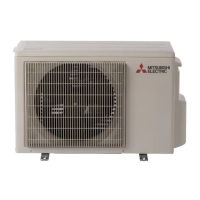
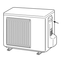
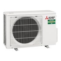
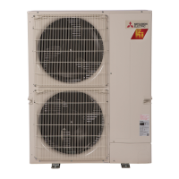
B.3 OUTDOOR UNIT (SUZ)..........................................................................B-85
SUZ-KA25VA
SUZ-KA35VA
SUZ-KA50VA
SUZ-KA60VA
SUZ-KA71VA
S series Model List

Other manuals for Mitsubishi Electric SUZ-KA50VA

Questions and Answers:

Mitsubishi Electric SUZ-KA50VA Specifications

General IconGeneral
CategoryAir Conditioner
ModelSUZ-KA50VA
TypeOutdoor Unit
Cooling Capacity5.0 kW
Power Source220-240V, 50Hz
Energy Efficiency Ratio (EER)3.21
Seasonal Energy Efficiency Ratio (SEER)6.1
RefrigerantR410A
Outdoor Unit Noise Level51 dB

Summary

S series Model List

B.1 600 x 600 CEILING CASSETTE (SLZ)

Details specifications and dimensions for the 600x600 Ceiling Cassette (SLZ) series.

B.2 CEILING CONCEALED (SEZ)

Details specifications and dimensions for the Ceiling Concealed (SEZ) series.

B.3 OUTDOOR UNIT (SUZ)

Details specifications and dimensions for the Outdoor Unit (SUZ) series.

B.1 600x600 CEILING CASSETTE (SLZ)

B.1.1 SPECIFICATIONS

Presents detailed technical specifications for the SLZ series units.

B.1.2 OUTLINES AND DIMENSIONS

Provides physical outlines and dimensional drawings for SLZ series units.

B.1.3 WIRING DIAGRAM

Illustrates the electrical wiring diagram for the SLZ series.

B.1.4 REFRIGERANT SYSTEM DIAGRAM

Details the refrigerant system diagram for the SLZ series.

B.1.5 PERFORMANCE DATA

Contains performance data tables for the SLZ series under various conditions.

B.1.6 4-WAY AIR FLOW SYSTEM

Explains the 4-way airflow system and its features for the SLZ series.

B.1.7 NOISE CRITERIA CURVES

Presents noise criteria curves for the SLZ series units.

B.1.8 OUTLET AIR SPEED AND COVERAGE RANGE

Details outlet air speed and coverage range for SLZ series units.

B.1.9 CENTER OF GRAVITY POSITION

Shows the center of gravity position for the SLZ series units.

B.1.10 REMOTE CONTROLLER

Explains the operation and features of the remote controller for SLZ series.

B.1.11 TROUBLESHOOTING

Provides troubleshooting steps and error codes for the SLZ series.

B.1.12 INSTALLATION PROCEDURE

Details the step-by-step installation procedures for SLZ series units.

B.1.2.1 INDOOR UNIT

Detailed outlines and dimensions of the SLZ series indoor unit.

B.1.2.2 WIRELESS REMOTE CONTROLLER

Outlines and dimensions for the wireless remote controller.

B.1.2.3 WIRED REMOTE CONTROLLER

Outlines and dimensions for the wired remote controller.

B.1.10.1 WIRELESS REMOTE CONTROLLER

Detailed explanation of the wireless remote controller functions.

B.1.10.2 WIRED REMOTE CONTROLLER

Detailed explanation of the wired remote controller functions.

1. CAUTIONS ON TROUBLESHOOTING

Important safety precautions to be observed before troubleshooting.

2. SELF-CHECK

Procedure for performing self-check on wired and wireless controllers.

[Output pattern A] Errors detected by indoor unit

Lists error codes and symptoms detected by the indoor unit.

[Output pattern B] Errors detected by unit other than indoor unit (outdoor unit, etc.)

Lists error codes and symptoms detected by the outdoor unit.

Symptom Cause

Details symptoms and causes for unit malfunctions.

1. Safety precautions

General safety precautions to be followed during installation.

2. Selecting the installation location

Guidance on selecting appropriate installation locations for indoor and outdoor units.

4. FIXING OF HORIZONTAL VANE

Procedure for setting and fixing the horizontal vane.

Setting procedure

Procedure for setting and fixing the horizontal vane.

Measured standard position of the grille

Shows the standard position for setting the grille vanes.

8. Installing the grille

Guidance on installing the grille, noting attachment position restrictions.

8.1. Check the grille accessories

Lists the accessories supplied with the unit grille.

8.2. Preparing to attach the grille

Steps for preparing to attach the grille, including alignment.

8.2.1. Removing the intake grille

Instructions for removing the intake grille from the unit.

8.2.2. Removing the corner panel

Procedure for removing the corner panel from the unit.

8.3. Installing the grille

Guidance on installing the grille, noting attachment position restrictions.

8.3.1. Preparations

Preparation steps before installing the grille, including screw placement.

8.3.2. Temporary installation of the grille

Steps for temporary installation of the grille.

8.3.3. Securing the grille

Procedure for securely attaching the grille to the main unit.

8.3.4. Wire connection

Instructions for connecting wires to the grille's connector.

8.4. Locking the up/down airflow direction

Procedure for setting and locking the up/down airflow direction.

9. Test run

Procedures for performing a test run of the installed unit.

9.1. Before test run

Checks to perform before starting the unit test run.

9.2. Test run

Procedure for conducting the test run for the unit.

9.2.1. For wireless remote controller

Test run procedures using the wireless remote controller.

Checking the remote (infrared) signal reception

How to check the reception of the remote controller's signal.

9.2.2. Wired remote controller

Test run procedures using the wired remote controller.

9.3. Check drainage

Procedure to check the drainage system functionality.

9.3.1. For wireless remote controller

Steps to check drainage using the wireless remote controller.

9.3.2. For wired remote controller

Steps to check drainage using the wired remote controller.

B.2 CEILING CONCEALED (SEZ)

B.2.1 SPECIFICATIONS

Presents detailed technical specifications for the SEZ series units.

B.2.2 OUTLINES AND DIMENSIONS

Provides physical outlines and dimensional drawings for SEZ series units.

B.2.3 WIRING DIAGRAM

Illustrates the electrical wiring diagram for the SEZ series.

B.2.4 REFRIGERANT SYSTEM DIAGRAM

Details the refrigerant system diagram for the SEZ series.

B.2.5 PERFORMANCE DATA

Contains performance data tables for the SEZ series under various conditions.

B.2.6 NOISE CRITERIA CURVES

Presents noise criteria curves for the SEZ series units.

B.2.7 INDOOR FAN PERFORMANCE AND CORRECTED AIR FLOW

Shows indoor fan performance and corrected airflow data for SEZ units.

B.2.8 CENTER OF GRAVITY POSITION

Shows the center of gravity position for the SEZ series units.

B.2.9 REMOTE CONTROLLER

Explains the operation and features of the remote controller for SEZ series.

B.2.10 TROUBLESHOOTING

Provides troubleshooting steps and error codes for the SEZ series.

B.2.11 INSTALLATION PROCEDURE

Details the step-by-step installation procedures for SEZ series units.

B.2.2.1 INDOOR UNIT

Detailed outlines and dimensions of the SEZ series indoor unit.

B.2.2.2 WIRED REMOTE CONTROLLER

Outlines and dimensions for the wired remote controller.

B.2.2.3 WIRELESS REMOTE CONTROLLER

Outlines and dimensions for the wireless remote controller.

1. CAUTIONS ON TROUBLESHOOTING

Important safety precautions to be observed before troubleshooting.

Check code

Lists and explains error codes detected by the units.

B.3 OUTDOOR UNIT (SUZ)

B.3.1 OUTLINES AND DIMENSIONS

Provides physical outlines and dimensional drawings for SUZ units.

B.3.2 WIRING DIAGRAM

Illustrates the electrical wiring diagram for the SUZ outdoor unit.

B.3.3 REFRIGERANT SYSTEM DIAGRAM

Details the refrigerant system diagram for the SUZ outdoor unit.

B.3.4 PERFORMANCE CURVES

Presents performance curves for SUZ outdoor units under various conditions.

B.3.5 NOISE CRITERIA CURVES

Presents noise criteria curves for SUZ outdoor units.

B.3.6 ACTUATOR CONTROL

Explains the control of actuators like fan motors and valves.

B.3.7 TROUBLESHOOTING

Provides troubleshooting steps and error codes for SUZ outdoor units.

B.3.8 EARTHQUAKE-PROOF STRENGTH ANALYSIS

Analysis of anchor bolt strength for earthquake resistance.

B.3.9 CAPACITY CORRECTION RATIO CURVE PIPING LENGTH

Shows capacity correction based on refrigerant piping length.

B.3.10 INSTALLATION PROCEDURE

Details the step-by-step installation procedures for SUZ outdoor units.

3. Installation diagram

Diagrams illustrating outdoor unit installation and service space.

3.1. Outdoor unit (Fig. 3-1)

Diagram illustrating the outdoor unit installation and service space.

4. Drain piping for outdoor unit (Fig. 4-1)

Instructions for outdoor unit drain piping installation.

5. Refrigerant piping work

Core installation task for refrigerant piping.

5.1. Refrigerant pipe

Details specifications and limitations for refrigerant piping.

5.2. Flaring work

Procedure for correct flaring work to prevent gas leakage.

5.2.1. Pipe cutting

Instructions for correctly cutting copper tubes for piping.

5.2.2. Burrs removal

Procedure for removing burrs from cut pipe sections.

5.2.3. Putting nut on

Instructions for putting flare nuts onto pipes before flaring.

5.2.4. Flaring work

Detailed steps for performing flaring work with a flaring tool.

5.2.5. Check

Guidance on checking the quality of flared work and redoing if necessary.

5.3. Purging procedures leak test

Procedures for purging and performing leak tests on refrigerant pipes.

6. Electrical work

Core installation task for electrical wiring.

6.1. Outdoor unit

Instructions for wiring connections to the outdoor unit.

6.2. Field electrical wiring

Details electrical wiring procedures for the outdoor unit.

7. Maintenance

Operational upkeep procedures for the unit.

7.1. Gas charge

Instructions for charging refrigerant into the system.

Related product manuals