Do you have a question about the Mitsubishi Electric SUZ-KA50VA2 and is the answer not in the manual?
| Brand | Mitsubishi Electric |
|---|---|
| Model | SUZ-KA50VA2 |
| Category | Air Conditioner |
| Language | English |
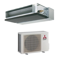
Details on service manuals for indoor units used in combinations.
Manual details specific tools required for R410A refrigerant, including differences from R22 tools.
Details on pipe diameter, wall thickness, and insulation material for refrigerant lines.
Specifies refrigerant oil type and procedures for air purging and additional refrigerant charge.
Table detailing electrical specifications, fan motor data, and other key components for each model.
Explains the ON/OFF timing for the outdoor fan motor relative to compressor operation.
Details the control logic for the reversing valve during heating, cooling, and dry modes.
Table showing how sensors relate to actuators for protection and operation.
Instructions on changing the defrost finish temperature by modifying a jumper wire.
Safety and handling precautions to be observed before and during troubleshooting procedures.
Guide on how to access and interpret error codes stored by the unit for diagnosis.
Correlates LED indications and symptoms with specific abnormal points and correspondence.
Details testing methods and criteria for diagnosing major components like thermistors and compressors.
Detailed step-by-step diagnostic flows for various system failures and component checks.
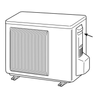
Step-by-step procedure for removing the outdoor unit cabinet panels for access.
Instructions for removing the inverter assembly, P.C. boards, and power board.
Procedure for disconnecting and removing the reversing valve (R.V.) coil.
Steps for safely removing discharge, defrost, heat exchanger, and ambient temperature thermistors.
Instructions for disconnecting and removing the outdoor fan motor assembly.
Procedure for recovering refrigerant and removing the compressor and 4-way valve.
Steps for disconnecting and removing the reactor component.
Diagram showing component layout and test points on the inverter P.C. board for SUZ-KA25/35VA2.TH.
Diagram illustrating component placement and test points on the inverter P.C. board for SUZ-KA50VA2.TH.
Diagram showing component layout and test points on the inverter P.C. board for SUZ-KA71VA2.TH.
Diagram of the outdoor electronic control P.C. board with component identification and connection points.
Diagram showing the layout and components of the noise filter P.C. board.
Diagram illustrating the layout and connections of the outdoor power board.
Troubleshooting steps for electromagnetic noise related to power supply issues.
Guide to resolve electromagnetic noise by checking indoor/outdoor unit wiring and connections.
Diagnostic steps for electromagnetic noise related to the R.V. coil.
Steps to diagnose electromagnetic noise by checking compressor and inverter operation.
Diagnostic steps for electromagnetic noise related to outdoor thermistors.
Diagnostic steps for electromagnetic noise related to the outdoor fan motor.
Diagnostic steps for electromagnetic noise related to the High Pressure Switch (HPS).
Diagnostic steps for electromagnetic noise related to the current-limiting resistor.
Steps to diagnose electromagnetic noise by checking inverter/compressor voltage and operation.
Diagnostic steps for electromagnetic noise related to compressor winding resistance.
Diagnostic steps for electromagnetic noise related to compressor operation time.
Diagnostic steps for electromagnetic noise related to compressor start failure.
Diagnostic steps for electromagnetic noise related to outdoor thermistors.
Diagnostic steps for electromagnetic noise related to the R.V. coil.
Diagnostic steps for electromagnetic noise related to the outdoor fan motor.
Diagnostic steps for electromagnetic noise related to power supply.
Diagnostic steps for electromagnetic noise related to the LEV coil.
Diagnostic steps for electromagnetic noise related to the inverter P.C. board.
Diagnostic steps for electromagnetic noise related to miswiring and serial signal errors.