EasyManua.ls Logo

Mitsubishi Electric SUZ-KA60VA2 User Manual

Mitsubishi Electric SUZ-KA60VA2
74 pages
To Next Page IconTo Next Page
Page #1 background imageLoading...
Page #1 background image
TECHNICAL & SERVICE MANUAL
No.OCH472
SPLIT-TYPE, HEAT PUMP AIR CONDITIONERS
R410A
Outdoor unit
[model names]
[Service Ref.]
SUZ-KA25VA2 SUZ-KA25VA2.TH
SUZ-KA35VA2 SUZ-KA35VA2.TH
SUZ-KA50VA2 SUZ-KA50VA2.TH
SUZ-KA60VA2 SUZ-KA60VA2.TH
SUZ-KA71VA2 SUZ-KA71VA2.TH
CONTENTS
1.
COMBINATION OF INDOOR AND OUTDOOR UNITS
.......
2
2. TECHNICAL CHANGES
....................................
3
3. PART NAMES AND FUNCTIONS
......................
6
4. SPECIFICATION
.................................................
7
5. NOISE CRITERIA CURVES
...............................
9
6. OUTLINES AND DIMENSIONS
........................
10
7. WIRING DIAGRAM
...........................................
13
8. REFRIGERANT SYSTEM DIAGRAM
..............
17
9. ACTUATOR CONTROL
....................................
21
10. SERVICE FUNCTIONS
.....................................
22
11. TROUBLESHOOTING
......................................
22
12. DISASSEMBLY INSTRUCTIONS
.....................
63
Indication of
model name
NOTE:
This service manual describes technical data of the
outdoor units.
RoHS compliant products have <G> mark on the spec
name plate.
For servicing of RoHS compliant products, refer to the
RoHS Parts List.
HFC
utilized
R410A
SUZ-KA25VA2.TH
SUZ-KA35VA2.TH
May 2010
PARTS CATALOG (OCB472)
Question and Answer IconNeed help?

Do you have a question about the Mitsubishi Electric SUZ-KA60VA2 and is the answer not in the manual?

Mitsubishi Electric SUZ-KA60VA2 Specifications

General IconGeneral
BrandMitsubishi Electric
ModelSUZ-KA60VA2
CategoryAir Conditioner
LanguageEnglish

Summary

Technical & Service Manual Overview

R410A Outdoor Unit Models

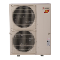
Lists outdoor unit models for R410A refrigerant.

1. Combination of Indoor and Outdoor Units

Indoor/Outdoor Unit Combinations

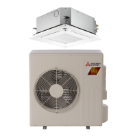
Details combinations of indoor and outdoor units for heat pump systems.

2. Technical Changes for R410A Refrigerant

R410A Refrigerant Information and Precautions

Key information and precautions for using R410A refrigerant in air conditioners.

R410A Refrigerant Tools and Specifications

Dedicated Tools for R410A Refrigerant

Table detailing tools required for R410A refrigerant and compatibility with R22 tools.

Refrigerant Piping and Handling

Refrigerant Piping Specifications and Charging Procedures

Specifies pipe requirements and procedures for refrigerant charging.

3. Part Names and Functions

Outdoor Unit Component Identification

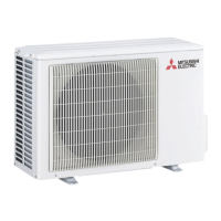
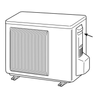
Illustrates part names for various outdoor unit models.

4. Specifications Overview

Outdoor Unit Performance Specifications

Lists specifications for different outdoor unit models including electrical, fan, and special remarks.

Main Electric Parts Specifications

Electric Component Ratings and Conditions

Details main electric parts and their specifications for various outdoor unit models.

5. Noise Criteria Curves

Noise Level Data by Model and Condition

Noise criteria curves for different outdoor unit models under cooling and heating conditions.

6. Outlines and Dimensions

Dimensions and Space Requirements (SUZ-KA25/35VA2.TH)

Outlines and dimensions for SUZ-KA25/35VA2.TH units, including required space.

Dimensions and Space Requirements (SUZ-KA50/60VA2.TH)

Dimensions and Space Requirements (SUZ-KA50/60VA2.TH)

Specifies dimensions and required installation space for SUZ-KA50VA2.TH and SUZ-KA60VA2.TH units.

Dimensions and Space Requirements (SUZ-KA71VA2.TH)

Dimensions and Space Requirements (SUZ-KA71VA2.TH)

Specifies dimensions and required installation space for SUZ-KA71VA2.TH unit.

7. Wiring Diagram

Wiring Diagrams (SUZ-KA25/35VA2.TH)

Wiring diagram for SUZ-KA25VA2.TH and SUZ-KA35VA2.TH outdoor units.

Wiring Diagram (SUZ-KA50VA2.TH)

Wiring Diagram (SUZ-KA50VA2.TH)

Wiring diagram for SUZ-KA50VA2.TH outdoor unit.

Wiring Diagram (SUZ-KA60VA2.TH)

Wiring Diagram (SUZ-KA60VA2.TH)

Wiring diagram for SUZ-KA60VA2.TH outdoor unit.

Wiring Diagram (SUZ-KA71VA2.TH)

Wiring Diagram (SUZ-KA71VA2.TH)

Wiring diagram for SUZ-KA71VA2.TH outdoor unit.

8. Refrigerant System Diagram

Refrigerant System (SUZ-KA25/35VA2.TH)

Refrigerant system diagram for SUZ-KA25VA2.TH and SUZ-KA35VA2.TH outdoor units.

Refrigerant System (SUZ-KA50/60VA2.TH)

Refrigerant System (SUZ-KA50VA2.TH)

Refrigerant system diagram for SUZ-KA50VA2.TH outdoor unit.

Refrigerant System (SUZ-KA60VA2.TH)

Refrigerant system diagram for SUZ-KA60VA2.TH outdoor unit.

Refrigerant System (SUZ-KA71VA2.TH)

Refrigerant System (SUZ-KA71VA2.TH)

Refrigerant system diagram for SUZ-KA71VA2.TH outdoor unit.

Refrigerant Piping Length and Charge Calculations

Maximum Piping Length and Additional Charge

Details maximum piping length and additional refrigerant charge required based on piping length for R410A.

9. Actuator Control

Actuator Control Logic and Sensor Relationships

Explains control for fan, R.V. coil, and sensor-to-actuator mapping.

10. Service Functions & 11. Troubleshooting Introduction

Defrost Setting Adjustment

Instructions on how to change the defrost finish temperature using a jumper wire.

Troubleshooting Cautions and Preparations

Important precautions and steps to follow before and during troubleshooting procedures.

11-2. Failure Mode Recall Function

Failure Mode Recall Procedure (Wireless Remote)

Flowchart illustrating the procedure for recalling failure modes using a wireless remote controller.

Failure Mode Tables and Wired Controller Use

Failure Mode Tables (Indoor and Outdoor Units)

Table listing error codes, symptoms, and remarks for indoor and outdoor unit failures.

11-2-4. Outdoor Unit Failure Mode Table

Outdoor Unit Failure Modes (SUZ-KA25/35/50VA2.TH)

Table detailing outdoor unit failure modes, LED indications, conditions, and correspondences for specific models.

Outdoor Unit Failure Modes (SUZ-KA60VA2.TH)

Abnormal Points and Conditions (SUZ-KA60VA2.TH)

Lists abnormal points and conditions for outdoor unit failures with LED indications.

Outdoor Unit Failure Modes (SUZ-KA71VA2.TH)

Abnormal Points and Conditions (SUZ-KA71VA2.TH)

Lists abnormal points and conditions for outdoor unit failures with LED indications.

11-3. Troubleshooting Check Table

Troubleshooting Table (SUZ-KA25/35/50VA2.TH)

Troubleshooting check table for specific outdoor unit models indicating LED patterns, conditions, and correspondences.

Troubleshooting Check Table (SUZ-KA60VA2.TH)

Troubleshooting Details (SUZ-KA60VA2.TH)

Troubleshooting check table for SUZ-KA60VA2.TH, detailing symptoms, LED indications, conditions, and correspondences.

Troubleshooting Check Table (SUZ-KA60VA2.TH Continued)

Troubleshooting Details (SUZ-KA60VA2.TH) Continued

Continues the troubleshooting table for SUZ-KA60VA2.TH, listing symptoms, LED indications, conditions, and correspondences.

Troubleshooting Check Table (SUZ-KA71VA2.TH)

Troubleshooting Details (SUZ-KA71VA2.TH)

Troubleshooting check table for SUZ-KA71VA2.TH, detailing symptoms, LED indications, conditions, and correspondences.

11-4. Trouble Criteria of Main Parts (1)

Trouble Criteria (SUZ-KA25/35VA2.TH)

Trouble criteria for main parts of SUZ-KA25VA2.TH and SUZ-KA35VA2.TH, including check methods and figures.

11-4. Trouble Criteria of Main Parts (2)

Trouble Criteria (SUZ-KA50/60/71VA2.TH)

Trouble criteria for main parts of SUZ-KA50VA2.TH, SUZ-KA60VA2.TH, SUZ-KA71VA2.TH.

11-5. Troubleshooting Flowcharts

Inverter/Compressor Check Procedure

Flowchart for checking the inverter and compressor, including voltage checks and common issues.

Component Diagnosis Procedures (1)

Compressor and Thermistor Checks

Measures compressor winding resistance, operation time, and checks outdoor thermistors.

Component Diagnosis Procedures (2)

R.V. Coil and Outdoor Fan Motor Checks

Checks the R.V. coil and outdoor fan motor's resistance, voltage, and rotation.

Power Supply and LEV Checks

Power Supply and LEV Verification

Verifies power supply and expansion valve (LEV) operation, sound, vibration, and coil resistance/voltage.

LEV and Inverter P.C. Board Diagnosis

LEV and Inverter P.C. Board Checks

Checks LEV operation and diagnoses inverter P.C. board issues by checking fuses, connectors, and LEDs.

Miswiring and Serial Signal Error Checks (Indoor Unit)

Indoor Unit Wiring and Signal Error Troubleshooting

Instructions for checking miswiring and serial signal errors related to the indoor unit.

Miswiring and Serial Signal Error Checks (Indoor Unit - Continued)

Indoor Unit Wiring and Signal Error Troubleshooting (Continued)

Continues checking for miswiring and serial signal errors related to indoor unit operation.

Electromagnetic Noise Troubleshooting

Diagnosing Electromagnetic Noise Issues

Guidelines for diagnosing electromagnetic noise issues, offering troubleshooting steps.

Power Supply Checks (SUZ-KA60VA2.TH)

Power Supply Troubleshooting Steps

Troubleshooting steps for checking the power supply cable, fuses, and reactor.

Miswiring/Signal Error Checks (SUZ-KA60VA2.TH - Indoor Unit)

Indoor Unit Operation Error Checks

Checks for miswiring and serial signal errors affecting the indoor unit's operation.

Miswiring/Signal Error Checks (SUZ-KA60VA2.TH - Indoor Unit Continued)

Indoor Unit Operation Error Checks (Continued)

Continues checking for miswiring and serial signal errors related to indoor unit operation.

R.V. Coil Troubleshooting (SUZ-KA60VA2.TH)

Heating Operation Troubleshooting

Troubleshooting steps for R.V. coil when heating operation fails.

Cooling Operation Troubleshooting

Troubleshooting steps for R.V. coil when cooling operation fails.

LEV and Inverter/Compressor Checks (SUZ-KA60VA2.TH)

LEV Operation Check

Checks the expansion valve (LEV) operation via sound, vibration, and coil resistance/voltage.

Inverter/Compressor Diagnosis

Procedure to check the inverter and compressor for issues affecting heating or cooling.

Outdoor Thermistor and Fan Motor Checks (SUZ-KA60VA2.TH)

Outdoor Thermistor Diagnosis

Diagnoses outdoor thermistor issues by checking resistance and operation.

Outdoor Fan Motor Diagnosis

Steps to diagnose problems with the outdoor fan motor not operating or stopping shortly after start.

HPS and Current-Limiting Resistor Checks (SUZ-KA60VA2.TH)

HPS Protection Check

Verifies HPS protection status and checks the electronic control P.C. board.

Current-Limiting Resistor Check

Troubleshooting steps for the current-limiting resistor and its associated relay.

Inverter/Compressor Checks (SUZ-KA71VA2.TH)

Open Phase and Compressor Checks

Procedure to check for open phase, winding, and continuous operation of the compressor.

Compressor Operation and Start Failure Checks (SUZ-KA71VA2.TH)

Compressor Operation Time and Start Failure Diagnosis

Measures compressor operation time and diagnoses start failures by checking circuits and conditions.

Outdoor Thermistor and R.V. Coil Checks (SUZ-KA71VA2.TH)

Outdoor Thermistor Diagnosis

Diagnoses outdoor thermistor issues by checking resistance and operation.

R.V. Coil Operation Check

Checks the R.V. coil for defects and proper operation in heating and cooling modes.

Outdoor Fan Motor and Power Supply Checks (SUZ-KA71VA2.TH)

Outdoor Fan Motor and Power Supply Diagnosis

Checks the outdoor fan motor and power supply to the unit.

LEV Checks (SUZ-KA71VA2.TH)

LEV Operation Check (Wireless/Wired)

Checks the expansion valve (LEV) operation via sound, vibration, and coil resistance/voltage.

Inverter P.C. Board Checks (SUZ-KA71VA2.TH)

Inverter P.C. Board Diagnosis

Diagnoses inverter P.C. board issues by checking fuses, connectors, and LED error codes.

Miswiring and Serial Signal Error Checks (SUZ-KA71VA2.TH)

Wiring and Signal Error Troubleshooting

Troubleshooting steps for miswiring and serial signal errors affecting unit operation.

Electromagnetic Noise Troubleshooting (SUZ-KA71VA2.TH)

Electromagnetic Noise Troubleshooting Steps

Guidelines for diagnosing electromagnetic noise issues, offering troubleshooting steps.

11-6. Test Point Diagram and Voltage

Inverter P.C. Board Test Points (SUZ-KA25/35VA2.TH)

Test point diagram and voltage information for the inverter P.C. board.

Inverter P.C. Board Test Points (SUZ-KA50VA2.TH)

Inverter P.C. Board Test Points (SUZ-KA50VA2.TH)

Test point diagram and voltage details for the inverter P.C. board.

Inverter P.C. Board Test Points (SUZ-KA71VA2.TH)

Inverter P.C. Board Test Points (SUZ-KA71VA2.TH)

Test point diagram and voltage information for the inverter P.C. board.

Outdoor Electronic Control P.C. Board Test Points (SUZ-KA60VA2.TH)

Outdoor Electronic Control P.C. Board Diagram

Test point diagram for the outdoor electronic control P.C. board.

Noise Filter P.C. Board Diagram (SUZ-KA60VA2.TH)

Noise Filter P.C. Board Diagram

Diagram of the noise filter P.C. board.

Outdoor Power Board Test Points (SUZ-KA60VA2.TH)

Outdoor Power Board Diagram

Test point diagram for the outdoor power board.

12. Disassembly Instructions

Terminal Detaching Procedures

Instructions on how to detach terminals with and without locking mechanisms.

Cabinet Removal (SUZ-KA25/35VA2.TH)

Operating procedure for removing the cabinet of SUZ-KA25VA2.TH and SUZ-KA35VA2.TH outdoor units.

Component Disassembly (SUZ-KA50/60VA2.TH)

Inverter Assembly, P.C. Boards, and Power Board Removal

Steps for removing the inverter assembly, P.C. boards, and power board.

R.V. Coil and Thermistor Removal

Procedures for removing the R.V. coil and various thermistors.

Component Disassembly (SUZ-KA50/60VA2.TH Continued)

Outdoor Fan Motor and Compressor Removal

Instructions for removing the outdoor fan motor, compressor, and 4-way valve.

Cabinet Removal (SUZ-KA50/60VA2.TH)

Cabinet Removal Procedure

Operating procedure for removing the cabinet of SUZ-KA50VA2.TH and SUZ-KA60VA2.TH outdoor units.

Component Disassembly (SUZ-KA50/60VA2.TH Continued)

Inverter, Control Boards, and R.V. Coil Removal

Steps for removing inverter, electronic control boards, and R.V. coil.

Component Disassembly (SUZ-KA71VA2.TH)

Thermistor and Fan Motor Removal

Steps to remove thermistors and the outdoor fan motor.

Component Disassembly (SUZ-KA71VA2.TH Continued)

Compressor, 4-Way Valve, and Reactor Removal

Steps to remove the compressor, 4-way valve, and reactor.

Cabinet Removal (SUZ-KA71VA2.TH)

Cabinet Removal Procedure

Operating procedure for removing the cabinet of SUZ-KA71VA2.TH outdoor unit.

Component Disassembly (SUZ-KA71VA2.TH Continued)

Inverter, P.C. Boards, and R.V. Coil Removal

Steps to remove the inverter assembly, P.C. boards, and R.V. coil.

Component Disassembly (SUZ-KA71VA2.TH Continued)

Thermistor, Fan Motor, Compressor, and Valve Removal

Steps to remove thermistors, fan motor, compressor, and 4-way valve.

Related product manuals