SERVICE MANUAL
SPLIT-TYPE, HEAT PUMP AIR CONDITIONERS
CONTENTS
1.
COMBINATION OF INDOOR AND OUTDOOR UNITS
...
2
2. PART NAMES AND FUNCTIONS
......................
2
3. SPECIFICATION
.................................................
3
4. OUTLINES AND DIMENSIONS
..........................
4
5. WIRING DIAGRAM
............................................
5
6. REFRIGERANT SYSTEM DIAGRAM
................
9
7. DATA
.................................................................
10
8. ACTUATOR CONTROL
....................................
12
9. SERVICE FUNCTION
.......................................
13
10. TROUBLESHOOTING
......................................
13
11. FUNCTION SETTING
.......................................
29
12. DISASSEMBLY INSTRUCTIONS
.....................
32
HFC
utilized
R410A
R410A
Note:
This service manual describes
service data of the outdoor units
only.
PARTS CATALOG (OCB699)
No. OCH699
December 2018
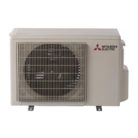
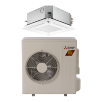
Outdoor unit
[Model Name]
SUZ-KA09NA2
SUZ-KA09NAH2
SUZ-KA12NA2
SUZ-KA12NAH2
SUZ-KA15NA2
SUZ-KA15NAH2
[Service Ref.]
SUZ-KA09NA2.MX
SUZ-KA09NAH2.MX
SUZ-KA12NA2.MX
SUZ-KA12NAH2.MX
SUZ-KA15NA2.MX
SUZ-KA15NAH2.MX
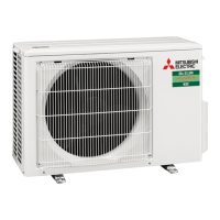
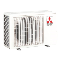
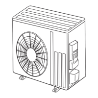
SUZ-KA09NA(H)2.MX
Air outlet
Drain outlet
Piping
Drain hose
Air inlet
(back and side)