EasyManua.ls Logo

Mitsubishi Electric SUZ-KA09NAH2.MX User Manual

Mitsubishi Electric SUZ-KA09NAH2.MX
36 pages
To Next Page IconTo Next Page
Page #1 background imageLoading...
Page #1 background image
SERVICE MANUAL
SPLIT-TYPE, HEAT PUMP AIR CONDITIONERS
CONTENTS
1.
COMBINATION OF INDOOR AND OUTDOOR UNITS
...
2
2. PART NAMES AND FUNCTIONS
......................
2
3. SPECIFICATION
.................................................
3
4. OUTLINES AND DIMENSIONS
..........................
4
5. WIRING DIAGRAM
............................................
5
6. REFRIGERANT SYSTEM DIAGRAM
................
9
7. DATA
.................................................................
10
8. ACTUATOR CONTROL
....................................
12
9. SERVICE FUNCTION
.......................................
13
10. TROUBLESHOOTING
......................................
13
11. FUNCTION SETTING
.......................................
29
12. DISASSEMBLY INSTRUCTIONS
.....................
32
HFC
utilized
R410A
R410A
Note:
This service manual describes
service data of the outdoor units
only.
PARTS CATALOG (OCB699)
No. OCH699
December 2018
Outdoor unit
[Model Name]
SUZ-KA09NA2
SUZ-KA09NAH2
SUZ-KA12NA2
SUZ-KA12NAH2
SUZ-KA15NA2
SUZ-KA15NAH2
[Service Ref.]
SUZ-KA09NA2.MX
SUZ-KA09NAH2.MX
SUZ-KA12NA2.MX
SUZ-KA12NAH2.MX
SUZ-KA15NA2.MX
SUZ-KA15NAH2.MX
SUZ-KA09NA(H)2.MX
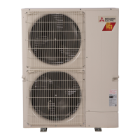
Air outlet
Drain outlet
Piping
Drain hose
Air inlet
(back and side)

Questions and Answers:

Mitsubishi Electric SUZ-KA09NAH2.MX Specifications

General IconGeneral
BrandMitsubishi Electric
ModelSUZ-KA09NAH2.MX
CategoryAir Conditioner
LanguageEnglish

Summary

Combination of Indoor and Outdoor Units

Part Names and Functions

Specification

Outlines and Dimensions

Wiring Diagram

Refrigerant System Diagram

Data

Actuator Control

Outdoor Fan Motor Control

Controls the outdoor fan motor's operation relative to the compressor's start and stop cycles.

R.V. Coil Control

Details the operation of the 4-way reversing valve (R.V. coil) during cooling and heating modes.

Relation Between Main Sensor and Actuator

Maps sensors to their corresponding actuators for system operation and protection.

Service Function

Change in Defrost Setting

Procedure to adjust the defrost finish temperature by modifying jumper settings.

Pre-Heat Control Setting

Enables/disables pre-heat control to prevent compressor issues in low outside temperatures.

Troubleshooting

Cautions on Troubleshooting

Important safety and preliminary checks before commencing troubleshooting procedures.

Trouble Shooting Check Table

Lists error symptoms, LED codes, conditions, and remedies for common malfunctions.

How to Proceed "Self-Diagnosis"

Guide on using the self-diagnosis function to recall and reset error history.

Self-Diagnosis <Wireless Remote Controller>

Instructions for performing self-diagnosis using the wireless remote controller.

Trouble Criterion of Main Parts

Provides resistance and voltage criteria for testing key components during troubleshooting.

Troubleshooting Flow

Flowcharts for diagnosing issues with the inverter, compressor, and related components.

Check of Outdoor Thermistors

Procedure for checking the resistance of various outdoor thermistors for proper function.

Check of R.V. Coil

Method for testing the R.V. coil for defects by checking voltage and resistance.

Check of Outdoor Fan Motor

Steps to test the outdoor fan motor's resistance, voltage, and rotation for proper operation.

Check of Power Supply

Procedure to verify power supply voltage and inverter P.C. board status for troubleshooting.

Check of LEV (Expansion Valve)

Testing the LEV coil for proper operation by checking for click sound and resistance.

Check of Inverter P.C. Board

Diagnostic steps for the inverter P.C. board, including fuse checks and LED indications.

How to Check Miswiring and Serial Signal Error

Troubleshooting guide for identifying and correcting miswiring and serial signal communication errors.

Check the Defrost Heater

Checks for proper operation of the defrost heater, including continuity and voltage checks.

Check of Outdoor Refrigerant Circuit

Troubleshooting steps for issues related to the outdoor refrigerant circuit, including pump down.

Electromagnetic Noise Enters into TV Sets or Radios

Guidance on identifying and mitigating electromagnetic noise interference with TV and radio reception.

Test Point Diagram and Voltage

Diagrams and charts showing test points, voltages, and thermistor resistance characteristics.

Function Setting

Unit Function Setting by the Remote Controller

Instructions for setting various unit functions using the remote controller interface.

Selecting Functions Using the Wired Remote Controller

Details on accessing and selecting functions via the wired remote controller's service menu.

Function Setting

Steps for setting unit functions, including refrigerant addresses and specific mode configurations.

Disassembly Instructions

SUZ-KA09NA(H)2.MX SUZ-KA12NA(H)2.MX SUZ-KA15NA(H)2.MX

Step-by-step guide for disassembling the outdoor unit cabinet and panels.

Removing the Inverter Assembly, Inverter P.C. Board

Instructions for safely removing the inverter assembly and its associated P.C. board.

Removing R.V. Coil

Procedure for removing the 4-way reversing valve (R.V. coil) from the unit.

Removing Thermistors

Steps for removing various temperature sensors from their holders.

Related product manuals