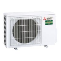
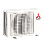
Do you have a question about the Mitsubishi Electric SUZ-M25VA and is the answer not in the manual?
| Brand | Mitsubishi Electric |
|---|---|
| Model | SUZ-M25VA |
| Category | Air Conditioner |
| Language | English |
Explains warning symbols used on the unit for safety.
General safety rules and precautions for handling the unit.
Specific guidelines for handling R32 refrigerant during service.
General warnings and prohibitions for service personnel.
Outlines essential safety checks and procedures for servicing R32 units.
Details checks for equipment using flammable refrigerants, including charge size and markings.
Procedures for safety checks and handling of electrical components during repair.
Guidelines for repairing sealed components, emphasizing safety and protection.
Rules for working with intrinsically safe components in flammable atmospheres.
Methods and precautions for detecting flammable refrigerant leaks safely.
Specific techniques and equipment for detecting refrigerant leaks with R32.
Procedures for safely removing and evacuating refrigerant from the system.
Steps for safely charging the system with refrigerant, including checks and precautions.
Procedures and safety measures for decommissioning equipment containing refrigerant.
Guidelines for safely recovering refrigerant using approved equipment and cylinders.
Specifies installation area requirements for indoor units based on refrigerant quantity.
Details technical specifications and ratings for key electrical components.
Provides maximum allowed lengths and height differences for refrigerant piping.
Details the required additional refrigerant charge based on piping length.
Step-by-step procedure for pumping down the refrigerant system before relocation or disposal.
Explains the control logic for the outdoor fan motor based on compressor operation.
Describes the control signals for the 4-way reversing valve during cooling and heating.
Maps sensors to their purposes and controlled actuators in the system.
Instructions on how to adjust the defrost finish temperature setting.
Important warnings and checks to perform before commencing troubleshooting.
A table listing symptoms, check codes, conditions, and remedies for troubleshooting.
Guides for using self-diagnosis functions with different controller types.
Procedures to diagnose remote controller functionality and communication.
Lists error codes and symptoms for indoor and outdoor unit issues.
Provides methods and criteria for checking the condition of major system components.
Step-by-step diagnostic flows and component checks for troubleshooting.
Guidance on troubleshooting electromagnetic noise interference with AV equipment.
Diagnostic steps for issues within the outdoor refrigerant circuit.
Diagram showing test points and voltage measurements on the inverter P.C. board for specific models.
Diagram showing test points and voltage measurements on the inverter P.C. board for other models.
Illustrates how to detach terminals with locking mechanisms.
Step-by-step instructions for removing the outdoor unit cabinet panels.
Procedures for removing the inverter assembly and its P.C. board.
Steps for removing the 4-way reversing valve coil.
Instructions for removing various temperature sensors from the unit.
Steps for disassembling and removing the outdoor fan motor.
Procedures for removing the compressor and the 4-way valve.
Steps for removing the Electronic Expansion Valve (LEV) assembly.
Instructions for removing the outdoor unit cabinet panels for different models.
Procedures for removing the inverter assembly and its P.C. board for different models.
Steps for removing the 4-way reversing valve coil for different models.
Instructions for removing temperature sensors for different models.
Steps for disassembling and removing the outdoor fan motor for different models.
Procedures for removing the compressor and 4-way valve for different models.




 Loading...