Do you have a question about the Mitsubishi Electric TRANE CITY MULTI TPMFYP006BM140F and is the answer not in the manual?
| Brand | Mitsubishi Electric |
|---|---|
| Model | TRANE CITY MULTI TPMFYP006BM140F |
| Category | Air Conditioner |
| Language | English |
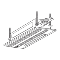
Air intake from outdoors for fresh, refreshing air.
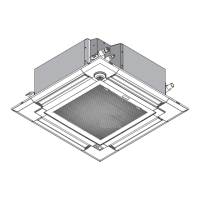
Lightweight and compact unit size for easier installation and maintenance.
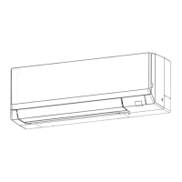
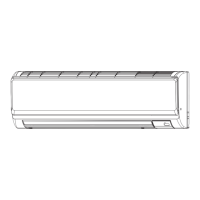
Identification and function of indoor unit parts like vanes, filters, and air intake.
Details the interface and functions of the TAR-40MAA wired remote controller.
Explains the purpose and operation of each button on the remote controller.
Explains the two display modes for the main display screen.
Describes the meaning of various icons shown on the remote controller display.
Guide to navigating main menu options like Operation, Timer, Energy saving, and Initial settings.
Access to Error information, Filter information, Test run, Maintenance information, and settings.
Specifics on Vane, Louver, Vent, High power, Comfort, and 3D i-see Sensor functions.
In-depth explanation of ON/OFF, Auto-Off, Weekly timer, and OU silent mode operations.
Configuration of Basic, Display, Operation, Restriction, Temp. range, and Schedule.
Explains Error info, Filter info, Test run, Maintenance info, and Check menus.
Details power, cooling/heating capacity, input, and current for different models.
Covers unit dimensions, heat exchanger, fan airflow, static pressure, and motor output.
Lists exterior materials, insulator, air filter, pipe dimensions, and noise levels.
Details for thermistors, fuse, motors, linear expansion valve, and terminal blocks.
Airflow (CFM) when taking air from outside for different models.
Explains booster fan operation and provides characteristic diagrams for air capacity.
Octave band sound pressure levels for different models and fan speeds.
Illustration of the setup used for measuring noise levels.
Detailed measurements of the indoor unit, including ceiling opening and suspension points.
Specifies the required space around the indoor unit for installation and service access.
Schematic showing connections for indoor unit components and power supply.
Details DIP switch settings (SW2, SW3, SW4, SW5) for different models and functions.
Illustrates the refrigerant flow and placement of components like thermistors and expansion valve.
Specifies the diameter of the gas and liquid refrigerant pipes for different models.
How to operate the unit in COOL mode using the remote controller.
Details temperature settings, anti-freeze control, and compressor time delay.
Explains the fan speed settings and options available.
How the drain pump operates and vane position control logic.
How temperature, fan, and freeze prevention are controlled in DRY mode.
How to operate the unit in FAN mode, including drain pump and vane control.
How to operate the unit in HEAT mode, including fan control.
Explains fan modes like Residual heat exclusion, Thermo OFF, and Heat defrosting.
Details drain pump operation and vane position restrictions during HEAT mode.
How to operate the unit in AUTO mode for automatic cool/heat changeover.
How the drain pump functions when the unit is stopped.
Procedures for checking thermistors and vane motor resistance.
Procedures for checking linear expansion valve and drain pump resistance.
Procedure for checking the drain sensor resistance.
Graphs and tables showing thermistor resistance vs. temperature.
Explanation of how the linear expansion valve operates and its connection.
Common issues like motor failure, locked valve, and connection problems.
Steps to check the fan motor, fuse, wiring, and voltage.
Settings for thermistor position, filter detection, fresh air intake, humidifier, and airflow.
Capacity code, Louver, Vane, Vane swing, angle, and heating settings.
How to set addresses using SW11, SW12 and branch numbers with SW14.
Setting the voltage selector (SW5) for 208V or 230V operation.
Labeled diagram of the indoor controller board with test points and connector locations.
Explains the purpose of various connectors (CN) and terminals (TB) on the board.
Diagram of the address board showing DIP switches and selectors.
Steps to open and remove the air intake grille, with figures.
Pre-installation checks for proper grille fit and insulation.
Steps to remove the grille, filter, screw cover, and securing screws.
Guide to reattaching the grille and performing final checks for gaps and filter installation.
Steps to remove the electrical parts box and disconnect associated wiring.
Detailed procedure for removing the nozzle, including insulation material and drain pan.
Steps for removing the drain pump, fan motor, and line flow fan.
Instructions for removing room, liquid pipe, and gas pipe thermistors.