EasyManua.ls Logo

Mitsubishi Electric TRANE TPKFYP006BM142B User Manual

Mitsubishi Electric TRANE TPKFYP006BM142B
34 pages
To Next Page IconTo Next Page
Page #1 background imageLoading...
Page #1 background image
TECHNICAL & SERVICE MANUAL
Notes:
This manual describes only
service data of the indoor
units.
R410A
Indoor unit
[Model Name]
TPKFYP006BM142B
April 2019
No. OCHT516
SPLIT-TYPE, HEAT PUMP AIR CONDITIONERS
INDOOR UNIT
Model name
indication
CONTENTS
1. SAFETY PRECAUTION
..........................
2
2. PARTS NAMES AND FUNCTIONS
........
3
3. SPECIFICATION
...................................
10
4. OUTLINES AND DIMENSIONS
............
13
5. WIRING DIAGRAM
...............................
14
6. REFRIGERANT SYSTEM DIAGRAM
........
15
7. MICROPROCESSOR CONTROL
.........
16
8. TROUBLESHOOTING
..........................
22
9. DISASSEMBLY PROCEDURE
.............
29
PARTS CATALOG (OCBT516)
Question and Answer IconNeed help?

Do you have a question about the Mitsubishi Electric TRANE TPKFYP006BM142B and is the answer not in the manual?

Mitsubishi Electric TRANE TPKFYP006BM142B Specifications

General IconGeneral
BrandMitsubishi Electric
ModelTRANE TPKFYP006BM142B
CategoryAir Conditioner
LanguageEnglish

Summary

Safety Precautions

Cautions Related to New Refrigerant

Important safety warnings and precautions for handling new refrigerants.

Parts Names and Functions

Indoor Unit Components

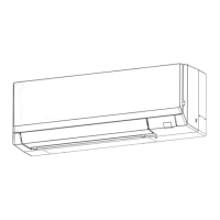
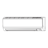
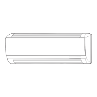
Identifies and describes the parts of the indoor unit.

Wired Remote Controller TAR-40MAA/TAC-YT53CRAU

Details functions of wired remote controllers TAR-40MAA and TAC-YT53CRAU.

Wired Remote Controller TAR-40MAA Interface

Explains the interface and buttons of the TAR-40MAA wired remote controller.

Specifications

General Unit Specifications

Provides technical data including capacity, power, dimensions, and materials.

Electrical Parts Specifications

Lists the specifications for electrical components of the unit.

Sound Levels and NC Curve

Presents sound level data and noise criteria (NC) curve for the unit.

Outlines and Dimensions

Unit Dimensions and Installation Details

Provides detailed physical dimensions and installation hole layouts.

Wiring Diagram

Indoor Unit Wiring Diagram

Illustrates the electrical connections and components within the indoor unit.

Refrigerant System Diagram

Refrigerant Flow and Components

Shows the refrigerant circuit and key components like strainers and expansion valves.

Microprocessor Control

Cool Operation Control

Explains the control logic and functions during cooling mode.

Dry Operation Control

Details the control logic and functions during dry mode.

Fan Operation Control

Describes how fan speed and vane position are controlled.

Heat Operation Control

Outlines the control logic and functions during heating mode.

Auto Operation Control

Explains the automatic switching between cooling and heating modes.

Troubleshooting

Checking Unit Parts

Guide on how to test electrical components like thermistors and motors.

Thermistor and Expansion Valve Diagnostics

Details thermistor characteristics and linear expansion valve operation for troubleshooting.

DIP Switch Functions

Details the functions controlled by various DIP switches.

Indoor Controller Board Test Points

Identifies test points on the indoor controller board for diagnostics.

Indoor Power and Address Board Layouts

Shows the physical layout and connections of indoor power and address boards.

Disassembly Procedure

Removing Lower Unit and Front Panel

Procedures for removing the lower indoor unit section and the front panel.

Removing Internal Boards and Assemblies

Steps to remove controller boards, power boards, nozzle, drain hose, and fan guard.

Removing Electrical Box and Fan Motor

Instructions for removing the electrical box and the fan motor assembly.

Removing Vane Motor and Temperature Sensors

Procedures for detaching the vane motor and pipe temperature sensors.

Related product manuals