EasyManua.ls Logo

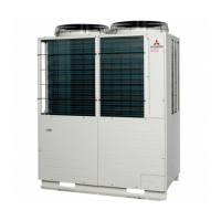
Mitsubishi Heavy Industries FDC280KXZE1 User Manual

Mitsubishi Heavy Industries FDC280KXZE1
169 pages
To Next Page IconTo Next Page
Page #1 background imageLoading...
Page #1 background image
VRF INVERTER MULTI-SYSTEM AIR-CONDITIONERS
(OUTDOOR UNIT)
Manual No. '14
KX-SM-202
Standard series
Single use (Used also for combination)
FDC280KXZE1, 335KXZE1, 400KXZE1, 450KXZE1, 475KXZE1, 500KXZE1, 560KXZE1
Combination use
FDC615KXZE1, 670KXZE1, 735KXZE1, 800KXZE1, 850KXZE1, 900KXZE1, 950KXZE1, 1000KXZE1,
1060KXZE1, 1120KXZE1, 1200KXZE1, 1250KXZE1, 1300KXZE1, 1350KXZE1,1425KXZE1,
1450KXZE1, 1500KXZE1, 1560KXZE1, 1620KXZE1, 1680KXZE1
KXZ series
(Heat pump type)
Corrosion protection treatment series (Non-CE Marking models)
Single use (Used also for combination)
FDCS280KXZE1, 335KXZE1, 400KXZE1, 450KXZE1, 475KXZE1, 500KXZE1, 560KXZE1
Combination use
FDCS615KXZE1, 670KXZE1, 735KXZE1, 800KXZE1, 850KXZE1, 900KXZE1, 950KXZE1, 1000KXZE1,
1060KXZE1, 1120KXZE1, 1200KXZE1, 1250KXZE1, 1300KXZE1, 1350KXZE1,1425KXZE1,
1450KXZE1, 1500KXZE1, 1560KXZE1, 1620KXZE1, 1680KXZE1
SERVICE MANUAL
INVERTER DRIVEN MULTI-OUTDOOR UNIT
CLIMATE CONTROL SYSTEM
Air-Conditioning & Refrigeration Systems
16-5, Konan 2-chome, Minato-ku, Tokyo, 108-8215 Japan
http://www.mhi.co.jp
Copyright MITSUBISHI HEAVY INDUSTRIES, LTD.
Because of our policy of continuous improvement, we reserve the right to make changes in all specifications without notice.
C
(1) Regarding the Indoor unit series, refer to the No.'14
KX-DB-206
(2) Regarding the Duct Connected-High static Pressure-type Outdoor Air Processing Unit Series
(FDU5001800FKXE6), refer to the DATA BOOK No.'08
KX-DB-122
Note:

Table of Contents

Question and Answer IconNeed help?

Do you have a question about the Mitsubishi Heavy Industries FDC280KXZE1 and is the answer not in the manual?

Mitsubishi Heavy Industries FDC280KXZE1 Specifications

General IconGeneral
BrandMitsubishi Heavy Industries
ModelFDC280KXZE1
CategoryAir Conditioner
LanguageEnglish

Summary

KXZ Series VRF Inverter Multi-System Air-Conditioners

Standard Series

Details on standard models of VRF inverter multi-system air conditioners.

Corrosion Protection Treatment Series

Information on non-CE marking models with corrosion protection treatment.

1. Operation Control by Microcomputer

1.1 Remote Control Operation

Explains operations using remote controls (wired and wireless).

1.2 Wired Remote Control Functions

RC-EX1A Remote Control Functions

Covers mode switching, CPU reset, and power failure compensation for RC-EX1A.

RC-E5 Remote Control Functions

Details operation and setting functions using the RC-E5 remote control.

1.3 Indoor Control Operations

Functional Items (Cooling/Heating)

Details component operations across cooling, heating, fan, and dehumidifying modes.

Timer Operations

Explains various timer settings for operation scheduling.

Hot Start Control

Procedures to prevent cold drafts during heating startup.

Thermostat Operation

Explains thermostat control logic for cooling and heating.

External Input/Output Control (CnT/CnTA)

Manages external signals for control functions like operation and emergency stop.

Operation Permission/Prohibition

Controls operation enablement/disablement via external inputs.

1.4 Outdoor Control Operations

Normal Control

Details major component operations across different modes (Cooling, Heating, Fan, Defrost).

Compressor Control (Master/Slave)

Order and conditions for compressor startup in single/multi-unit systems.

Defrosting Control (Master/Slave)

Specifies temperature thresholds for initiating and ending defrost cycles.

Protective Controls

Details safety controls for pressure, temperature, and current limits.

Auto Backup Operation

System's automatic operation backup during anomalies.

Test Run Procedures

Steps for performing test runs for heating and cooling.

Option Controls

Configuration of external input terminals for various control functions.

External Input & Demand Input

Manages external signals for operation permission, prohibition, and demand control.

Silent Mode Control

Controls unit operation to reduce noise levels.

Outdoor Operation Mode

Determines the outdoor unit's operation mode (Stop, Cooling, Heating).

(10) VTCC: Variable Temperature & Capacity Control

Target High/Low Pressure Correction

Adjusts target pressures for efficient operation based on indoor load.

(C) Data Output

7-Segment Display & Operation Data

Explains how to display and interpret operational data via the 7-segment display.

2. System Troubleshooting Procedure

2.1 Basics of Troubleshooting

General approach to troubleshooting using a Mente PC.

2.2 Troubleshooting Explanation

Explains troubleshooting steps for PCB and transistor module issues.

2.3 Troubleshooting Contents

Table of error codes, inspection names, classification, and pages.

Troubleshooting Flowcharts

Diagnostic flowcharts for common operational issues.

2.4 Outdoor Unit Control PCB Replacement

Step-by-step Instructions and Safety

Step-by-step instructions and safety for replacing the outdoor control PCB.

2.5 Outdoor Unit Inverter PCB Replacement

Instructions and Safety Precautions

Instructions and safety precautions for replacing the outdoor inverter PCB.

2.6 Outdoor Unit Transistor Module Replacement

Procedure for Replacing Transistor Module

Procedure for replacing the outdoor unit transistor module.

3. Electrical Wiring

Wiring Diagrams

Diagrams illustrating electrical connections for various models.

4. Piping System

Piping Layout Diagrams

Diagrams showing the piping layout for different system configurations.

4. Refrigerant Piping

Restrictions on Pipe Usage

Guidelines for pipe material, size, length, and elevation differences.

Pipe Connection Position & Direction

Correct positions and directions for pipe connections.

Air Tightness Test & Purge

Procedures for performing air tightness tests and purging the system.

4. Refrigerant Piping

Piping Work Procedures

Steps for cutting pipes, brazing, and handling refrigerant.

Air Tightness Test & Purge Procedures

Detailed procedures for air tightness testing and vacuuming.

4. Refrigerant Piping

Method of Operating Service Valves

Steps for correctly opening and closing service valves.

6. Electrical Wiring Work

6-1. Wiring System Diagrams

Diagrams illustrating wiring connections for indoor/outdoor units and controls.

6-2. Power Cable Connection Method

Guidelines for connecting power cables, including size and torque.

6-3. Signaling Wire Connection Method

Instructions for connecting signal wires for communication and control.

7. Controller Settings

7-1. Unit Address Setting

Procedures for setting addresses for outdoor and indoor units in Superlink systems.

7-2. Change of Control

How to modify control settings using PCB DIP switches and 7-segment indicators.

7-3. External Input and Output Terminals

Specifications and functions of external input/output terminals.

8. Test Operation and Transfer

8-2. Check Operation

Procedures for performing system check operations.

8-3. Refrigerant Quantity Check

Methods for checking and adjusting refrigerant levels.

8-4. Test Operation

Steps for initiating and terminating cooling test runs.

8-5. TRANSFER

Instructions for transferring system knowledge to the customer.

9. Servicing Cautions (R410A)

Important Safety and Maintenance Precautions

Important safety and maintenance precautions for R410A systems.

5.2 Installation Branch Pipe Set

Branch Pipe Set Installation Instructions

Instructions and parts list for installing branch pipe sets.

5.3 Front Panel Removal/Attachment

Procedure for Front Panel Removal and Attachment

Step-by-step guide for removing and attaching the front panel.

Related product manuals