30
Electrical installation
Connection between indoor unit and controller
See Connection for RC-HY20/40
Cascade connection setting
In case of cascade connection system, it is necessary to allot
unique address to each indoor unit. Set the dip switch S3-1, -2
and -3 according to the following table.
Address S3:1 S3:2 S3:3
1 OFF OFF OFF
2 On OFF OFF
3 OFF On OFF
4 On On OFF
5 OFF OFF On
6 On OFF On
7 OFF On On
8 On On On
Recommended fuse size for HSB140
The recommended fuse size shown in the following table is
reference value. Choose appropriate size according to local
laws and regulations.
Fuse size
Indoor unit (HSB140) 6A / 230V 1AC 50Hz
Outdoor unit (FDCW140VNX) 30A / 230V 1AC 50Hz
Controller (RC-HY20/40) 10A/ 230V 1AC 50Hz
Electric heater (ELK9M)
(reference)
16 A/400V 3NAC 50Hz
Recommended cable size for HSB140
The recommended cable size shown in the following table is
reference value. Choose appropriate size according to local
laws and regulations.
Cable size
Power – Indoor unit 3core, 1.5mm
2
(power cable)
Power – Outdoor unit 3core, 6.0mm
2
(power cable)
Indoor unit – Outdoor unit
2core, 1.5mm
2
(communication cable)
Indoor unit – Controller
3core, 0.5mm
2
, LiYY, EKKX or
equivalent (communication cable)
RC-HY20/40
Cable connection is diff erent according to the system structure.
Refer to the connection method according to the indoor unit.
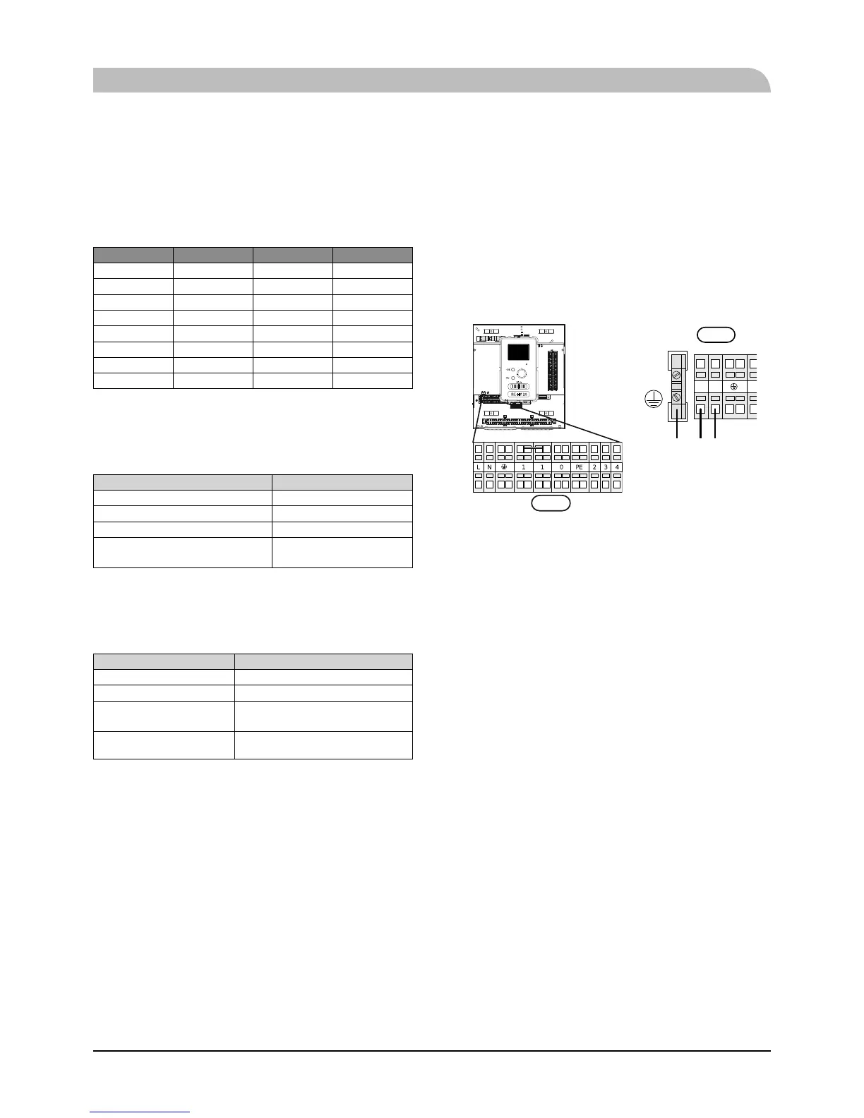
Power supply
HSB140
Connect power cable on X1 terminal as shown below.
RC-HY 20/40 must be installed via an isolator switch with a
minimum breaking gap of 3 mm. Minimum cable area must be
sized according to the fuse rating used.
NL
X1
RC-HY20/40
X1
 Loading...