7.
INITIAL SETTING
OF
TRANSMISSION CONTROL DATA TO
BUFFER MEMORY
MELSEC-A
7.
INITIAL
SETTING
OF
TRANSMISSION
CONTROL
DATA TO
BUFFER
MEMORY
The buffer memory has a special applications area for setting transmission
control data for communications with external devices (see Section 3.7).
Each transmission data item
has
a default value. However (depending on the
purpose and application
of
data transmission), using default values not only
makes data communications more complicated, but may even preclude them.
This section describes the settings of all Items In the buffer memory special
applications area, shows how to make changes, and gives specific examples.
The following sections give detailed information about the special applications
area:
.Section 8.14 gives details about the special applications area used for the
on-demand function when dedicated protocols are used.
.Section 9.5
(5)
gives details about the no-protocol received data clear
request area when the no-protocol mode is used.
.Section 10 gives details about the special applications area when
the
bidirectional mode
is
used.
~OINTS
I
(1) This section also discusses changing the default values set in the
special-applications area in the buffer and reading the present values
of the special-applications area.
It
is not necessary to write setting values to an area where default
values do not have to be changed.
(2) When changing a setting (except for the
two
areas indicated below),
either (a) turn
ON
the power supply or reset the PC CPU and change
the setting after the AJ71C24 READY signal
(Xn7)
goes
ON,
or (b)
switch the AJ71C24 mode and change the setting after the higher
bytes in the designated mode switching area of the AJ71C24 buffer
are moved into
02H.
.Error LED turn-OFF request area (address 102H)
.Mode switching designation area (address 11 9H)
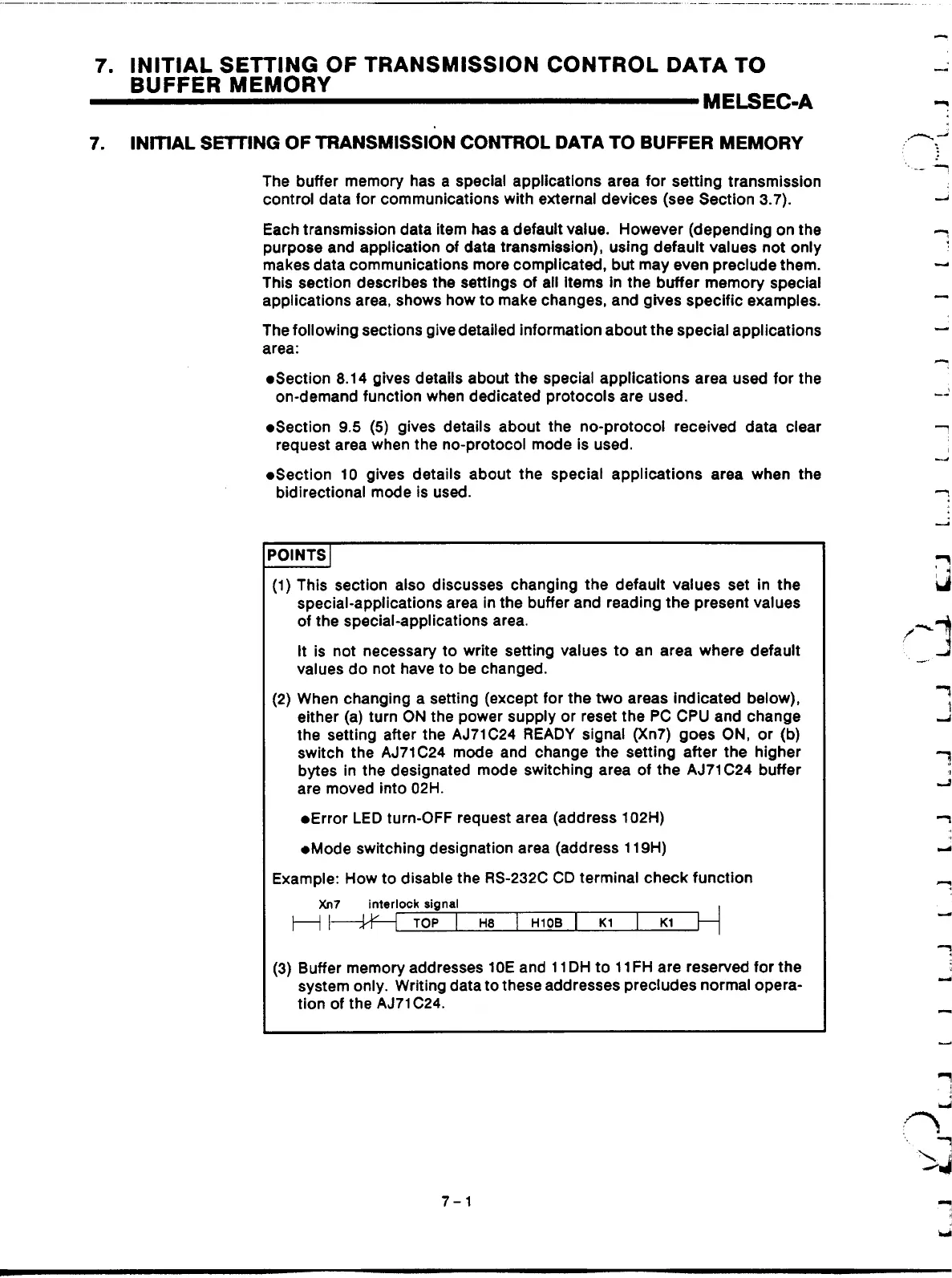
Example:
How
to disable the RS-232C CD terminal check function
H
I-
Xn7
interlock
signal
TOP
I
H8
I
(3)
Buffer memory addresses 10E and 11 DH to 11 FH are reserved for the
system only. Writing data to these addresses precludes normal opera-
tion of the AJ71 C24.
7-1
Artisan Technology Group - Quality Instrumentation ... Guaranteed | (888) 88-SOURCE | www.artisantg.com
 Loading...


