7.
INITIAL SETTING
OF
TRANSMISSION CONTROL DATA
TO
BUFFER
MEMORY
MELSEC-A
7.7.2
Sflings
for
changing
the
addresses
of
DC1
to
DC4
coder
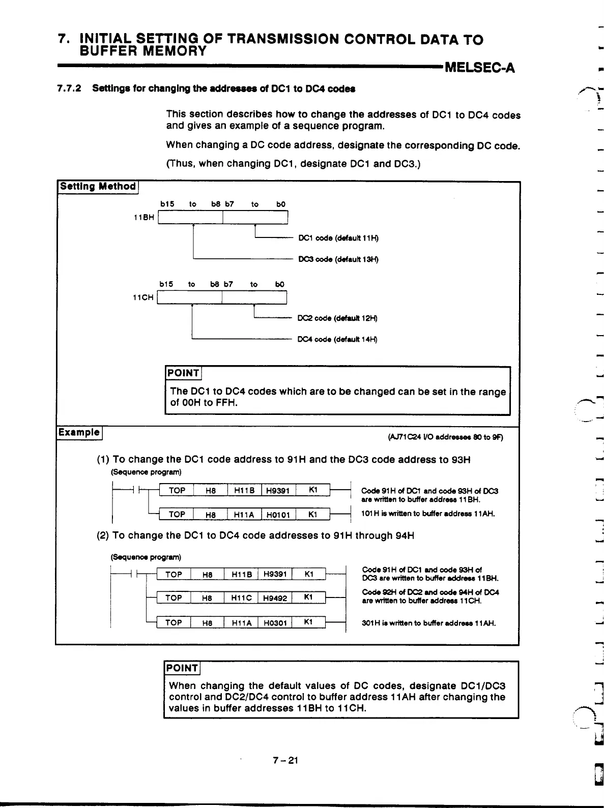
This section describes how to change the addresses of DC1 to DC4 codes
and gives an example
of
a sequence program.
When changing a DC code address, designate the corresponding DC code.
(Thus, when changing DC1, designate DC1 and DC3.)
Setting
Method]
8H
,b15
I;
b8, b7
t;
b0,
DC1
code
(default 11
H)
DC3
cede
(default 13H)
llCH
,blS
ti
M,b7
t;
bo,
DC2
code
(defu~H
12H)
DC4
code
(default 14H)
POINT]
The DC1
to
DC4 codes which are to be changed can be set
in
the range
of
OOH to FFH.
ixampie
I
(An1 C24
VO
addr-
80
to
SF)
(1) To change the DC1 code address to 91H and the DC3 code address to 93H
(-wen= program)
C0&9lHdKland&93HdDC3
are
mitten
to
buffer addrwa 11 BH.
101 H
is
written
to
buffer address 11AH.
(2) To change the DC1 to DC4 code addresses to 91 H through
94H
(Ssquew pTogr4
Code91HofDClandtxde93Hof
DC3
are
written
to
buffer
eddm
1 1
BH.
CodsS2HdDC2MdWdO94HdDC4
are
mitten to buffer address 11
CH.
301 H
k
written
to
buffer addrera 11
AH.
IPOINT~
When changing the default values
of
DC codes, designate DCl/DC3
control and DC2/DC4 control to buffer address 11AH after changing the
values in buffer addresses 11 BH to 11 CH.
Y
c.
Y
c.l
7-21
Artisan Technology Group - Quality Instrumentation ... Guaranteed | (888) 88-SOURCE | www.artisantg.com
 Loading...


