Sistema
α
2
AL2-GSM-CAB 8
ESP-39
ESP
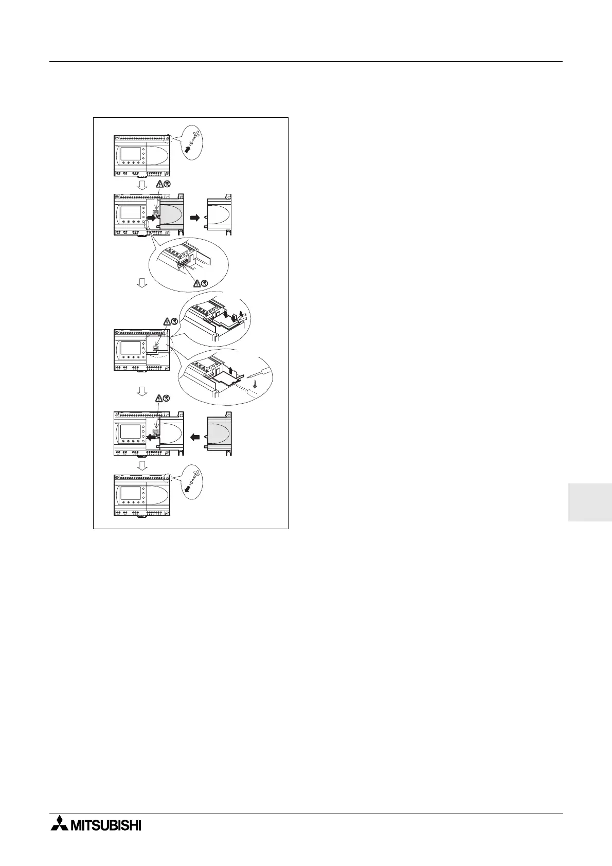
Figura 8.4: Installation
1) Retire el tornillo ‘A’ y guárdelo para el uso futuro.
2) Retire cuidadosamente la cubierta del puerto de
expansión
α
2 instalado en fábrica o la cubierta
del módulo especial.
3) Inserte el AL2-GSM-CAB en la cavidad
colocando el cable cuidadosamente en el canal
ubicado por el lado del terminal de entrada.
4) Vuelva a colocar la cubierta
α
2 ó la del módulo
especial cuidando que no se produzca una
interferencia con el AL2-GSM-CAB.
5) Vuelva a colocar el tornillo ‘A’ y apriételo con un
torque de 0,4 Nm.
OUT1
OK
-
+
ESC
OUT3
9
RELAY
OUTPUT
65
OUT
8
OUT2 OUT4
7
DC INPUT
151413121110987654321(B )(A )
+-
24V D C
POW ER
AL2-24MR-D
A
AL2-24MR-D
POW ER
24V D C
-+
(A)(B)123456789101112131415
DC INPUT
7
OUT4OUT2
8
OUT
56
OUTPUT
RELAY
9
OUT3
ESC
+
-
OK
OUT1
OUT1
OK
-
+
ESC
OUT3
9
RELAY
OUTPUT
65
OUT
8
OUT2 OUT4
7
DC INPUT
151413121110987654321(B )(A )
+-
24V D C
POW ER
AL2-24MR-D
A
1)
2)
3)
4)
5)
In s e rte
Retire
AL2-24M R-D
POW ER
24V D C
-+
(A)(B)123456789101112131415
DC INPUT
7
OUT4OUT2
8
OUT
5
OUTPUT
RELAY
9
OUT3
ESC
+
-
OK
OUT1
AL2-24M R-D
POW ER
24V D C
-+
(A) (B) 1 2 3 4 5 6 7 8 9 10 11 12 13 14 15
D C IN P U T
7
OUT4OUT2
8
OUT
5
OUTPUT
RELAY
9
OUT3
ESC
+
-
OK
OUT1
6
 Loading...


