α
2 Simple Application Controllers
Key, System Bit and Function Block Lists 10
ENG-51
ENG
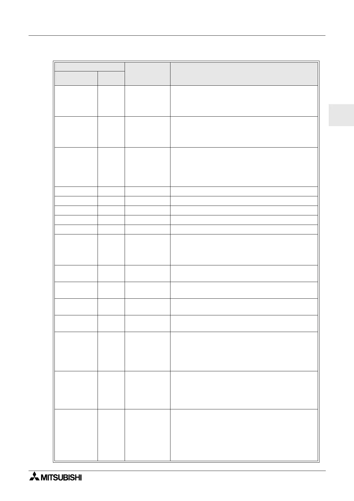
Speed Detect SPD 25
The signal input frequency (On/Off) is measured for a
set length of time. The frequency is compared to a
value range and the Output is turned ON/OFF
accordingtotheresult.
Pulse Width
Modulation
PWM 16
A continuous pulse train is output when this function
block is driven. The characteristics of the pulse are
defined as; Pulse duty (Direct set, Analog, FB values),
cycle time.
Retentive
Alternate
RAL 13
Output alternates turning ONorOFF with each input
pulse. The last output status is kept when the power
supply is cycled OFF and ON.
However, last output status is lost when the
α
2series
is placed in the Stop mode.
Addition ADD 20 y = A + B
Subtraction SUB 20 y = A-B
Multiplication MUL 20 y = A × B
Division DIV 20 A ÷ B = q, r (quotient and remainder)
Calculation CAL *4 Equation using +, −, ×, ÷, % and the selected data.
Shift SFT 19
Shift operation; When “SFT” signal is input, last “I”
signal status is output.
When using 8 bit shift operation, “Shift” function block
should be continued 8 times.
GSM SMS SMS *5
The contents of an LCD screen is sent as an SMS
message.
Random One
Shot
ROS 19 The random length single pulse is output.
Delayed One
Shot
DOS 20 After a delay time, send a single pulse
Delayed
Alternate
DAL 16
After a delay time, output alternates turning ONorOFF
with each input pulse
Retentive
Set/Reset
RSR 14
Latch a relay in SET or RESET position, give Set or
Reset priority. The last output status is kept when the
power supply is cycled OFF and ON.
However, last output status is lost when the
α
2series
is placed in the Stop mode.
Control
Display
CDP *6
Control which Display screen appears on the LCD.
This function block can only be set in the AL-PCS/
WIN-E software.
When control bit N04 is ON, it possible to control the
displayed User Screen.
Connect _B10
This CONNECT function block is an internal FB used
to show the memory used by the system bits, the bits
for AS-interface, and the operation keys. No function
block appears on screen or shows as being used in the
“Memory Configuration Usage” dialog box, the
purpose is only to calculate the memory that is used by
the bits listed above.
Table 10.4: Function Block Lists
Function Block Memory
Consumption
(Byte)
Description
Name Symbol
 Loading...


