Sistema
α
2
AL2-GSM-CAB 8
ITL-38
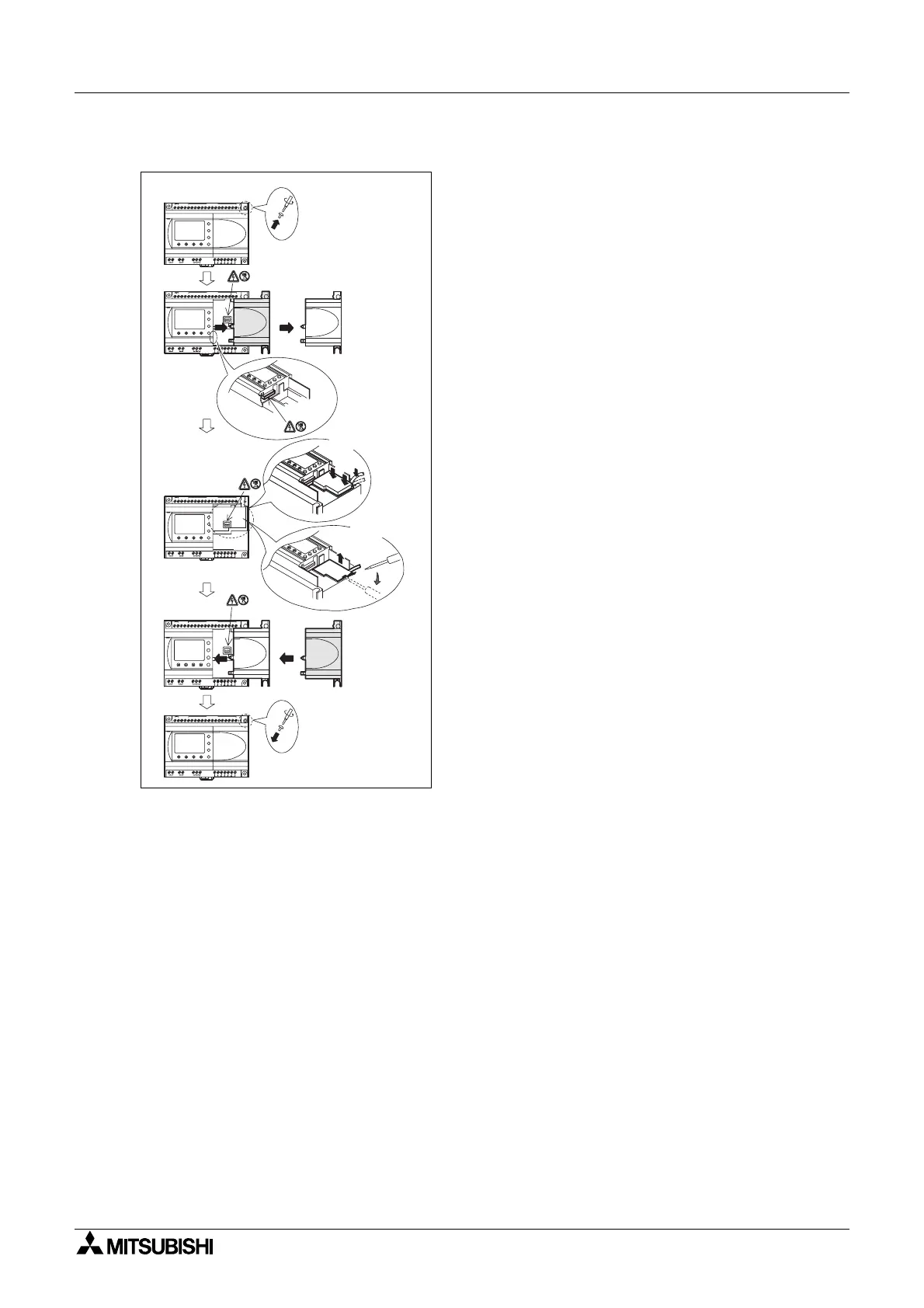
Illustrazione 8.4: Installation
1) Togliere la vite ‘A’ e conservarla per uso
successivo.
2) Togliere con cautela Rimuovere con cautela la
mascherina della porta di espansione montata in
fabbrica o il coperchio speciale del modulo
3) Installare lo AL2-GSM-CAB nella cavitá,
mettendo con cautela il cavo nel canaletto
sistemato sul lato del terminal di input.
4) Rimettere il coperchio
α
2 o il modulo speciale,
facendo attenzione che non ci siano interferenze
conloAL2-GSM-CAB.
5) Riavvitare la vite ‘A’ e serrare con coppia di 0.4
N·m.
OUT1
OK
-
+
ESC
OUT3
9
RELAY
OUTPUT
65
OUT
8
OUT2 OUT4
7
DC INPUT
151413121110987654321(B )(A )
+-
24V D C
POW ER
AL2-24MR-D
A
AL2-24MR-D
POW ER
24V D C
-+
(A)(B)123456789101112131415
DC INPUT
7
OUT4OUT2
8
OUT
56
OUTPUT
RELAY
9
OUT3
ESC
+
-
OK
OUT1
OUT1
OK
-
+
ESC
OUT3
9
RELAY
OUTPUT
65
OUT
8
OUT2 OUT4
7
DC INPUT
151413121110987654321(B )(A )
+-
24V D C
POW ER
AL2-24MR-D
A
1)
2)
3)
4)
5)
In s ta lla r e
R im uovere
AL2-24M R-D
POW ER
24V D C
-+
(A)(B)1 23456789101112131415
D C IN P U T
7
OUT4OUT2
8
OUT
5
OUTPUT
RELAY
9
OUT3
ESC
+
-
OK
OUT1
AL2-24M R-D
POW ER
24V D C
-+
(A)(B)123456789101112131415
DC INPUT
7
OUT4OUT2
8
OUT
5
OUTPUT
RELAY
9
OUT3
ESC
+
-
OK
OUT1
6
 Loading...


