α
2 Simple Application Controllers
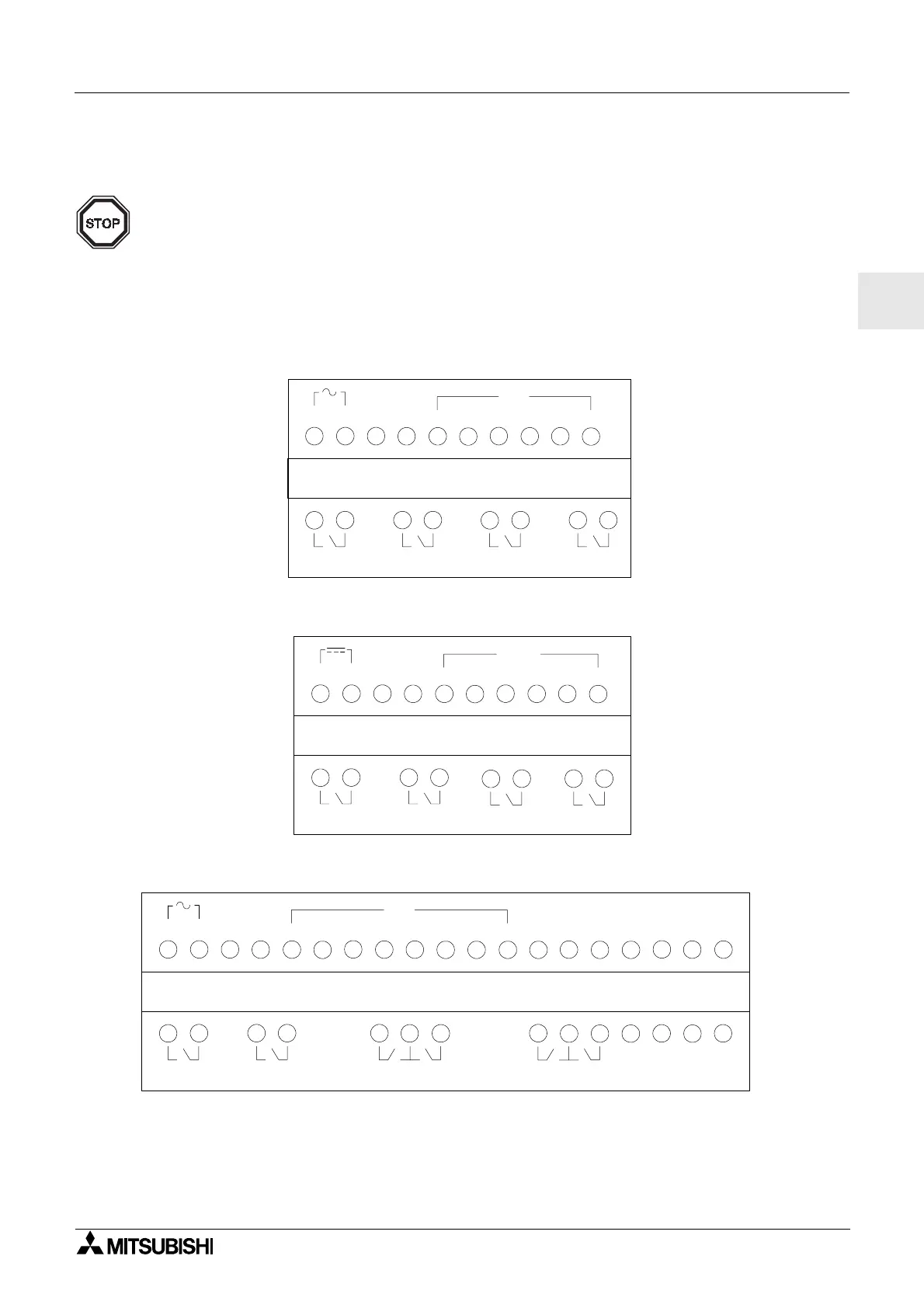
Terminal Layout 5
ENG-27
ENG
5. Terminal Layout
Note;
• Refer to chapter 9 about terminal layout of the AL2-ASI-BD.
• Refer to chapter 11 about terminal layout of the AL2-2DA.
• Refer to chapter 12 about terminal layout of the AL2-2PT-ADP.
• Refer to chapter 13 about terminal layout of the AL2-2TC-ADP.
Figure 5.1: AL2-10MR-A, AC Input, Relay Output
Figure 5.2: AL2-10MR-D, DC Input, Relay Output
Figure 5.3: AL2-14MR-A, AC Input, Relay Output
LN
IN
1
2
345
6
OUT1
OUT2
AL2-10MR-A
OUT3 OUT4
+-
IN
1
2
345
6
OUT1
OUT2
OUT3 OUT4
AL2-10MR-D
(A)
(B)
LN
IN
1
2
345
6
7
8
OUT1
OUT2
OUT3
OUT5
OUT4 OUT6
AL2-14MR-A
 Loading...


