α
2 Simple Application Controllers
DCF77 Radio Clock 10
ENG-50
Caution
• The AC version of the α2 series cannot be used to receive DCF77 radio signals.
• Only analog inputs that are available with the DC version of the α2 series can be used
to decode DCF77 radio signals.
For further Front programming details please refer to the
α2 Programming Manual
(JY992D97101).
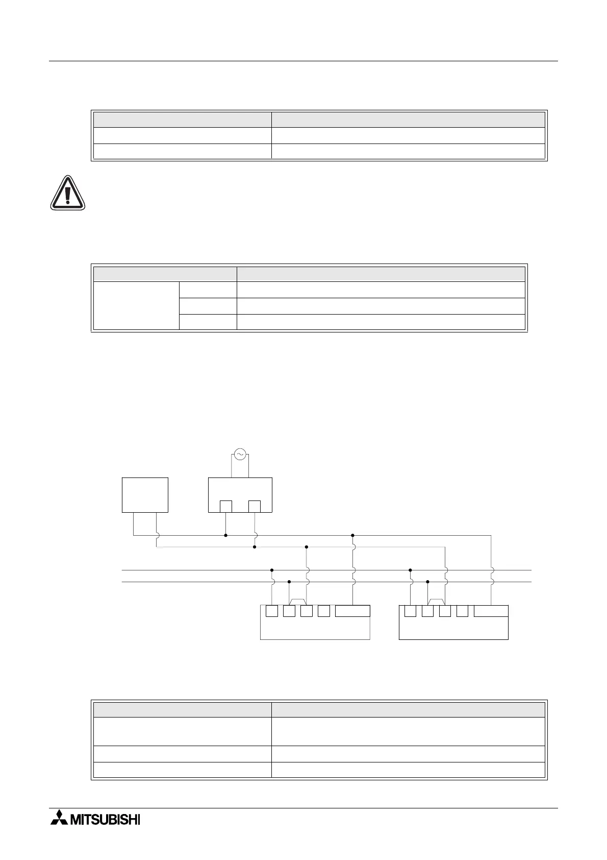
10.4 Wiring
10.4.1 Wiring
Figure 10.2: Wiring
The
α2 series controller must be wired for a source configuration, otherwise, the DCF77 signal
will not be received and decoded at the analog inputs.
Table 10.4: Applicable Version
PLC Type Applicable version
α2 Series (DC Version only) V2.00 or later
VLS Software V2.30 or later
Table 10.5: Software Specifications
Item Content
System Bit
M10 “ON” during DCF77 decoding
M11 Pulses “ON” when DCF77 finishes decoding without an error
M15 “ON” when DCF77 finishes decoding an error
Table 10.6: Wiring conditions
Item Description
α2 Series Antenna signal inputs
AL2-10MR-D:I01 - I06
AL2-14MR-D,AL2-24MR-D:I01 - I08
Max. α2 Series controllers 10 units
Max. wiring distance from antenna 200m
DCF 77
Antenna*
NT DCF 77
Power-pack*
+ -
α
2
+ -
A B I01-I08
α
2
+ -
A B I01-I08
24V+
24V-
* Manufactured by Theben AG
 Loading...


