α
2 Simple Application Controllers
AL2-GSM-CAB 8
ENG-39
ENG
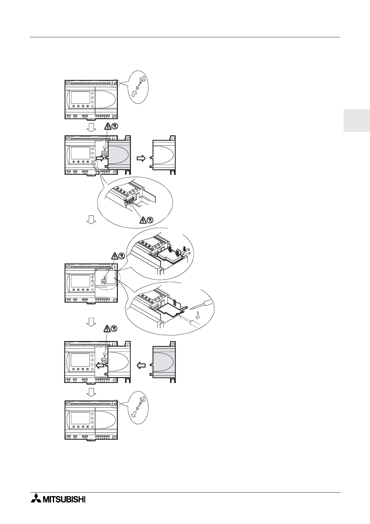
Figure 8.4: Installation
1) Release screw ‘A’ and keep.
2) Carefully remove the factory fitted
α2 expansion port cover or special
module cover.
3) Install the AL2-GSM-CAB
into the
cavity, carefully placing the cable in
the channel located on the input
terminal side.
4) Attach the
α2 cover or expansion
module taking care that there is no
interference with the AL2-GSM-
CAB.
5) Tighten screw ‘A’ to a torque of 0.4
N·m.
OUT1
OK
-
+
ESC
OUT3
9
RELAY
OUTPUT
65
OUT
8
OUT2 OU T4
7
DC INPUT
151413121110987654321(B)(A)
+-
24V DC
POWER
AL2-24MR-D
A
AL2-24MR-D
POWER
24V DC
-+
(A) (B) 1 2 3 4 5 6 7 8 9 10 11 12 13 14 15
DC INPUT
7
OUT4OUT2
8
OUT
56
OUTPUT
RELAY
9
OUT3
ESC
+
-
OK
OUT1
OUT1
OK
-
+
ESC
OUT3
9
RELAY
OUTPUT
65
OUT
8
OUT2 OU T4
7
DC INPUT
151413121110987654321(B)(A)
+-
24V DC
POWER
AL2-24MR-D
A
1)
2)
3)
4)
5)
Install
Remove
AL2-24MR-D
POWER
24V DC
-+
(A)(B)12345678 9101112131415
DC INPUT
7
OUT4OUT2
8
OUT
5
OUTPUT
RELAY
9
OUT3
ESC
+
-
OK
OUT1
AL2-24MR- D
POWER
24V DC
-+
(A) (B) 1 2 3 4 5 6 7 8 9 10 11 12 13 14 15
DC INPUT
7
OUT4OUT2
8
OUT
5
OUTPUT
RELAY
9
OUT3
ESC
+
-
OK
OUT1
6
 Loading...


