51
40
36
100
370 4040
410 2020
55
60
325262
38
76
190 580 200
60
15
103 15
50
27
52
11050
195
L1
L3
Intake
Outlet
Intake
Minimum installation space
space
Service
L2
L3
L4
L1
300
150
5
Open
I
Ⅱ
Open
5
150
500
Ⅲ
Open
5
300
5
Examples of
Dimensions
installation
L2
L4
20
845
10
110
50
195
242
279
970
50 16
55
Terminal block
67
7050
150
40
8
Notes
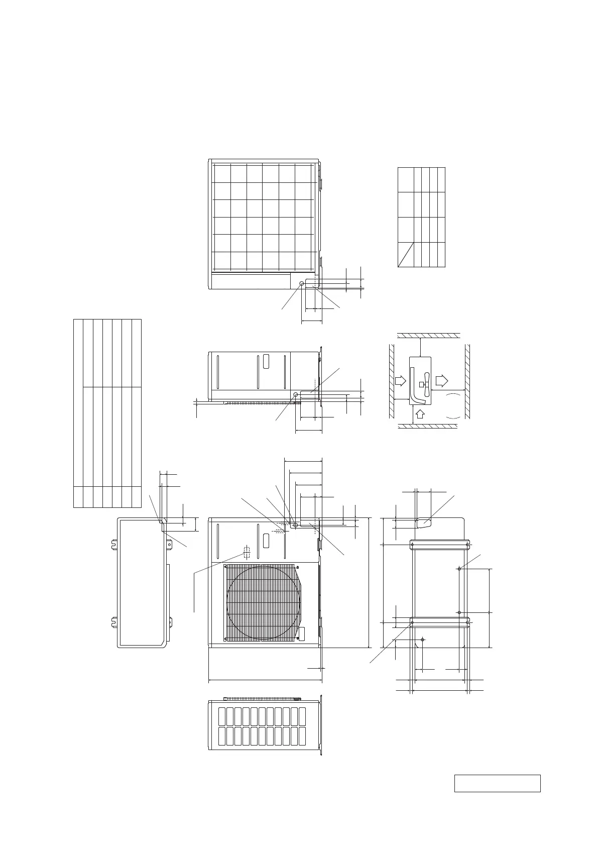
(1) It must not be surrounded by walls on the four sides.
( 2) The unit must be fixed with anchor bolts. An anchor bolt must
not protrude more the 15mm.
( 3) Where the unit is subject to strong winds, lay it in such
a direction that the blower outlet faces perpendicularly
to the dominant wind direction.
( 4) Leave 1m or more space above the unit.
( 5) A wall in front of the blower outlet must not exceed the units
height.
( 6) The model name label is attached on the lower right corner of
the front panel.
φ15.88(5/8")( Flare)
Content
C Pipe/cable draw-out hole
D
E Anchor bolt hole
Drain discharge hole
Mark
Meaning of marks
B
A Service valve connection(gas side)
M10×4 places
φ20×3 places
Service valve connection(liquid side)
φ9.52(3/8")( Flare)
F Cable draw-out hole
φ30×3 places
Unit:mm
E
C
D
F
B
A
C
C
A
B
F
C
F
2.2 Exterior dimensions
All models
PCA001Z900
-
7
-

 Loading...


