81
MECHANICAL STRUCTURE
7-4 Hydraulic Pump
1. Outline
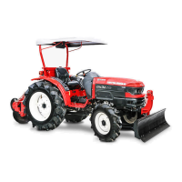
Gear Pump has two gears in mesh, closely fitted inside housing. The drive shaft drives the drive gear, which
in turn drives the driven gear. The shaft bushing and machined surfaces or side plates are used to seal in the
working gears.
As the gears rotate and come out of mesh, they trap inlet oil between the gear teeth and housing. The
trapped oil is carried around to the outlet chamber. As the gears mesh again they form a seal which prevents
oil from backing up to the inlet.
The oil forced out at the outlet port and sent through the system.
Pump Actuation View
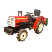
Drive Gear
Driven Gear
Drive Shaft
Inlet
Outlet
Bush
Pump Sectional View
Cover
Gear (B)
Side Plate
O-Ring
3 Shape of Seal
2. Sub Pump (For Power Steering)
Pump Model Gear Type
Model
KAYABA INDUSTRY
KPN05 60 ARMS
Discharge Amount 6.0cc / rev {0.366in
3
/rev}
Relief Pressure 15.2MPa {155kgf/cm
2
,2205pis}
Rotaing Direction Left (from the pump shaft side)
Application For Power Steering
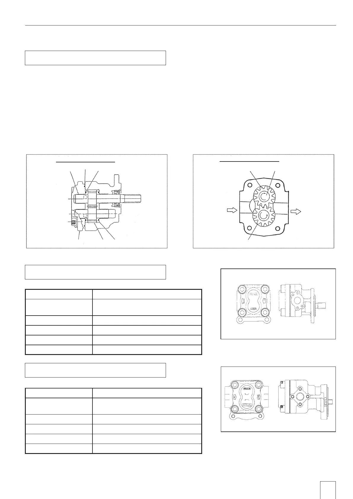
3. Main Pump (For Power Lift)
Pump Model Gear Type
Model
KAYABA INDUSTRY
KPN05 132C
Discharge Amount 13.2cc / rev {0.805 in
3
/rev}
Relief Pressure 15.2MPa {155kgf/cm
2
,2205pis}
Rotaing Direction Right (from the pump shaft side)
Application For Hydraulic Cylinder
 Loading...