Do you have a question about the Mitsubishi 1540 FD and is the answer not in the manual?
Detailed steps for starting and stopping the engine, including pre-checks, cold weather starts, and safety features.
Explanation of all dashboard instruments, warning lamps, switches, and levers for tractor operation and monitoring.
Covers the operation of key systems including clutch, brakes, transmission, differential lock, and PTO.
Guidance on tire installation, tread adjustment, ballast weight, and tire pressure for optimal performance.
Details on the three-point linkage, drawbar, and the tractor's hydraulic system for operating implements.
Detailed specifications for the Mitsubishi K3B diesel engine, including displacement, bore/stroke, horsepower, and torque.
Details on the cooling system (thermostat, pump) and fuel system components (pump, filter, tank capacity).
Specifications for lubrication system, air cleaner, governor, and electrical components like battery and starter.
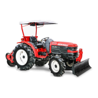
Measurements for chassis dimensions, tread, tire sizes, loads, and pressures for 2WD and 4WD models.
Technical data on clutch type, torque, transmission, brakes, steering systems, and PTO specifications.
Specifications for the hydraulic system, 3-point linkage, and drawbar pull ratings.
Lists all fluid capacities (oil, fuel, coolant) and provides traveling speed data in KM/Hr, M/s, and MPH.
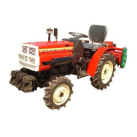
This document is an owner's manual for the Mitsubishi 1540 FD Agricultural Machinery Corporation tractor, providing comprehensive information on its operation, lubrication, and maintenance. It emphasizes the importance of understanding the manual, especially the "Safety Precautions" section, to prevent accidents and ensure the tractor's longevity and performance.
The manual outlines several critical safety precautions for operating the tractor. When running at high speeds or on roads, it is crucial to interlock the right and left brake pedals to prevent independent operation. A guard must always be in place when operating the belt pulley or PTO driven shaft. Operators should wear relatively tight and belted clothing to avoid entanglement with moving parts. Before leaving the tractor, the engine must be stopped, the parking brake applied, and the starting key removed. Sharp turns at high speeds should be avoided, and when descending a slope in reverse, the clutch or brake should not be operated abruptly. The differential lock should never be engaged on public roads and must be disengaged before making sharp turns. Operating the tractor on dangerous slopes requires extreme caution, avoiding abrupt clutch, brake, throttle lever, and steering wheel movements, especially on slippery surfaces. Passengers should not be carried on the tractor, linkage drawbars, or implements. When towing, the hitch point must be set below the rear axle's center line. Refueling requires stopping the engine and taking special care to prevent fuel ignition, using a safe fuel container, filling outdoors, wiping up spilled fuel, and securely replacing the fuel cap. Engine parts should not be touched until they have cooled sufficiently after operation. The positive battery post must always be covered with its rubber boot. The tractor engine should never be operated in a closed building due to carbon monoxide fumes. Children and untrained adults should not operate the tractor. When mounting implements, the instructions in the implement operation manual must be followed. For 4-WD tractors on roads, the front drive shift lever must be in the OFF position.
The manual serves as a guide for operating, lubricating, and maintaining the Mitsubishi 1540 FD tractor. It is designed to assist all users, including those without prior experience, in effectively utilizing the machine. The manual stresses that the tractor's performance and service life depend heavily on proper operation and maintenance. Regular servicing is essential to prevent major breakdowns, which can be more costly than routine maintenance. For any information or assistance, users are advised to consult their local dealer or distributor, providing the machine and engine serial numbers.
Before starting the engine, operators must check the fuel level, engine and transmission oil levels, and coolant water level. Daily maintenance, as described in Section 2, should also be performed.
The tractor is equipped with a safety starter switch to prevent accidental starts. This switch acts as a circuit breaker, ensuring the engine starting system circuit remains open unless the clutch is fully disengaged.
To start the engine:
The engine's fuel injection pump features a mechanism for easier cold starting by injecting excess fuel when the throttle lever is fully pulled. For cold weather starts, fully pull the throttle lever, adequately heat the glow plug, and then crank the engine.
Notes:
Important:
To stop the engine, idle it for a while by setting the speed control lever appropriately, then move the throttle lever fully to the "STOP" position to cut off fuel. Always turn the starter key to "OFF" after stopping the engine. When leaving the tractor, apply the parking brake and remove the key.
Tractor Meter: Located on the instrument panel, it displays engine speed in rpm (upper portion) and accumulated running hours at rated engine speed (lower center).
Oil Pressure Warning Lamp: Glows yellow when the starter key is "ON" and turns off when oil circulates normally during engine operation. If it remains on or lights up after starting, stop the engine immediately to check the oil level, oil pressure switch, and cabling. Replace defective components as needed.
Battery Charge Warning Lamp: Glows red when the starter switch is "ON" and turns off when the battery is charging normally. If it continues to glow, stop the engine and inspect the alternator, regulator, and cabling, replacing any defective parts.
Water Temperature Warning Lamp: Does not illuminate with the starter key in "ON" under normal conditions. It lights up to indicate overheating if the coolant temperature rises abnormally. Check the coolant level and fan belt, and recondition as necessary.
Caution: Exercise extreme care when removing the radiator cap from an overheated engine.
Light Switch: Located on the left side of the instrument panel, it controls headlights (off, on, dimmed). The working lamp switch is integrated into the light itself.
Safety Starter Switch: Prevents accidental engine starts by interrupting the starter motor circuit unless the clutch pedal is fully depressed, ensuring power to the transmission is completely disengaged.
Glow Plug: Sheathed glow plugs preheat the combustion chamber for easier cold weather starting.
Glow Signal: Indicates the glow plug's heating status on the instrument panel, visible through the heating condition of the glow signal resistance wire.
Throttle Lever: Pulling the throttle lever fully towards the operator increases engine speed to a maximum of 2,900 rpm. The rated engine speed for the K3B model is 2,700 rpm, which is recommended for optimal service life and fuel economy.
Foot Throttle: Located on the right side of the step, it allows free control of engine speed when the hand throttle is at idling. If the hand throttle is in a high revolution mode, the foot throttle will move to that position, preventing control below the hand throttle's set revolutions.
Clutch: Fully depressing the clutch pedal brings the machine to a complete halt for gear shifting in the transmission, PTO, and 4-WD. Half-engaging the clutch or shifting gears at high speed when the tractor is overloaded can damage the clutch lining. Declutching should be a complete, quick movement with lowered engine revolutions. When not in use, the clutch should be disengaged by depressing the pedal and hooking the clutch lever to prevent linings from sticking.
Brakes: Internal expansion (drum and shoe) type, dirt and water-proof. Two pedals on the right side of the transmission case, interlocked by a locking plate, apply the brakes. To stop the tractor, lower engine revolutions, depress the clutch, then the brake pedal. For shorter braking distances, quickly lower engine revolutions, depress the brake pedal, then the clutch pedal just before stopping. For turning in confined spaces, the right and left axles can be braked independently by disengaging the locking plate. When traveling at high speed or on roads, ensure the brake pedals are interlocked. Before road travel after independent brake use, check brake balance. Failure to check brake balance or interlock pedals can lead to accidents.
Parking Brake: To park, interlock the right and left brake pedals with the locking plate. While depressed, lock the pedals with the parking brake lever. To release, depress the brake pedal further and push the parking brake lever forward.
8-Speed Transmission: Offers six forward and two reverse speeds through a combination of main and sub shift levers. Low position of the sub shift lever provides first, second, third forward speeds and first reverse speed. High position provides fourth, fifth, sixth forward speeds and second reverse speed. When shifting gears, lower engine speed and depress the clutch pedal to disengage the transmission clutch. Shift gears only after the tractor has stopped.
Differential Lock: Links the right and left wheels to rotate at the same speed, preventing slipping and increasing traction.
Engaging the Differential Lock: Depress the pedal with your right foot to engage the differential lock before the tractor slips or speed lowers. If it doesn't engage initially, repeat more forcibly. If still unsuccessful, lower engine speed after disengaging the running clutch and repeat.
Releasing the Differential Lock: Automatically releases by spring force when the pedal is released. If it doesn't release, alternately and quickly depress the right and left brake pedals. During plowing, depress the pedal on the unplowed side. With interlocked brakes, turning the steering wheel sharply left and right will release it. If these methods fail, reverse the tractor a short distance.
Caution: Do not use the differential lock at high speeds or on roads.
The PTO shift lever, on the upper left of the transmission case, allows selection of three PTO speeds: 565 rpm, 832 rpm, or 1,364 rpm. When shifting, fully depress the clutch pedal to interrupt engine power and ensure the machine is completely stopped. Standard PTO speeds are 540 rpm at 2580 engine RPM (First) and 1,000 rpm at 1979 engine rpm (Third).
Notes:
The 4-Wheel Drive shift lever is on the right side of the clutch housing and operates similarly to the main, sub, and PTO shift levers.
Adjustable in three stages of 28mm (1.10”) to suit the operator's stature.
Located under the operator's seat. To access, turn the seat downward to the front.
Rear Tread: Adjustable by swapping left and right wheels, applicable to 2-WD or 4-WD with ES or AG tires.
Front Tread: Not adjustable.
AG tires must be mounted so that the lugs form staggered V's when viewed from the front of the tractor.
Minimizing tire slipping is crucial for efficiency and fuel economy. Ballast weights are optional and recommended for conditions prone to slipping. They can be attached to the front (2-WD AG only), rear wheel discs, and the front of the chassis. Water can also be added to tires for ballast, but pay attention to temperature and air pressure. In cold weather (below 0°C/32°F), use water with anti-freeze and never fill with water only. A combination of water and ballast weights can be used. Consult your dealer for water injection methods.
Check tire pressure frequently (at least once a week) as incorrect pressure can deteriorate tires.
The tractor features a Category 1 three-point link. Implements must match this size. When towing an implement with the linkage drawbar installed on lower links, the lower links should always be kept horizontal.
The tractor uses a "live" hydraulic system, providing hydraulic energy whenever the engine runs, with the pump directly mounted on the timing gear case. The factory-filled oil is SAE #80 gear oil, identical to the transmission system oil, filtered through a 100-mesh oil filter. Lift, hold, and down control are managed by the hydraulic control lever on the right side of the operator's seat. Down speed control and implement locking are managed by the flow control knob. External hydraulic operations, such as front-end loaders, can be performed via the PT3/8 tap hole.
Mechanism and Operation of the Hydraulic System: Understanding the hydraulic mechanism is essential for proper tractor operation.
Lift: Moving the hydraulic control lever fully backward forces hydraulic oil to the cylinder. When the implement reaches a specific position, the control valve automatically shifts to neutral via the feedback rod, holding the implement in the lift position.
Down: Moving the hydraulic control lever fully forward allows hydraulic oil to flow from the cylinder back to the tank through the control valve.
Hold: When the implement is fully raised, the control valve is in neutral, allowing the implement to be held at any desired position during upward or downward movement.
Flow Control Valve: Located in front of the hydraulic case under the seat, this knob controls the implement's lowering speed. Turning it clockwise slows lowering and, if turned further, closes the valve, holding the implement in place. Turning it counter-clockwise increases lowering speed.
Installing the External Hydraulic Adapter (Optional): To use the hydraulic adapter, loosen three bolts on the left side of the hydraulic case, remove the cap (careful not to drop the O-ring), fit the O-ring correctly to the adapter, and install it on the hydraulic case. Tighten to 2.5~3.0 kg-m (18~22 ft-Lb). Connect the external hydraulic adapter's outlet, the implement's control valve inlet, the control valve's outlet, and the external hydraulic adapter's oil return port with pipes. Start the engine, operate the implement's control valve to bleed air from the cylinder and pipes, then check for oil leaks at pipe joints.
Note: The external hydraulic adapter requires the implement to have a double-action control valve.
External Hydraulic Service: When using the tractor's hydraulic valve, it is a single-action type, so the implement must also be single-action. Connect the hydraulic external service plug and cylinder plug of the implement with a rubber hose. Relieve the auto-return of the hydraulic control lever by moving the locknuts backward on the auto-return rod. Start the engine, place the control lever in the lift position, operate the safety valve to bleed air from the cylinder and pipes, and lock the flow control knob. When the hydraulic control lever is in "Lift," the implement moves upward; in "Down," it moves downward.
Note: The hydraulic control lever does not automatically return to "Neutral." It must be manually returned to "Neutral" when the implement reaches maximum height. Leaving it in "Lift" will activate the relief valve, causing hydraulic oil temperature to rise and potentially damaging the machine.
A permanent drawbar is standard. Always use it to pull attachments or trailers.
Always install the PTO guard for safety during any operation.
Available for both 2-WD and 4-WD. When assembling, install the flange to the rubber coupling with the boss facing forward. Contact your dealer for details.
Note: Cut off the steel band in the rubber coupling after installation.
The standard muffler setting part is square. Install the standard muffler vertically upright and add an optional tail pipe to use it as an up-swept muffler.
Regular maintenance is crucial for the tractor's optimal condition, performance, and reliability. Neglecting periodic servicing will reduce performance and operating life, increasing the likelihood of major breakdowns and higher repair costs. Maintenance procedures are simple and essential.
This section contains detailed service information for the tractor.
This section provides instructions for properly storing the tractor.
| Engine Power | 40 hp |
|---|---|
| Drive | 4WD |
| Engine Type | Diesel |
| Cylinders | 3 |
| Type | Tractor |
| PTO Speed | 540 rpm |