13
Set the air outlet selection switch to .Set the air outlet selection switch to .
Air blows out automatically from the upper and lower air outlets as shown in the table below.
1.How to set to blow out air from the upper
and lower air outlets:
2.How to set to blow out air from the upper
air outlet only:
COOL DRY HEAT
Operation
Air
flow
Conditions
Upper and lower air flow
Room temperature
and set temperature
are different.
Upper air flow
Room temperature is
close to set tempera-
ture, or the air
conditioner has
operated for 1 hour.
Upper air flow only
Upper and lower air flow
Air flow temperature
is high.
Upper air flow
Air flow temperature
is low.
(During defrosting
operation, start of
operation, etc.)
• Be sure to keep the area around the damper of the lower air outlet free of any objects. If any objects block the normal
operation of the damper, the left operation indicator lamp may blink.
NOTE 2: Set the air outlet selection switch to the end correctly. Otherwise, air outlet cannot be selected as intended.
Description of operation
The direction (opening and closing of the damper) and the volume of the airflow from the lower air outlet are controlled auto-
matically.
• When installing a grating, use a grating
with narrow upper and lower horizontal
bars so that the airflow from the upper
and lower air outlets does not contact
the bars. If the horizontal bars will block
the lower air outlet, use a stand, etc., to
adjust the height of the indoor unit. If the
upper or lower air outlet is blocked, the
air conditioner will not be able to cool or
warm the room well.
• Do not block the receiver with the grat-
ing. Otherwise, the grating will interfere
with the remote controller signal and sig-
nificantly reduce the distance and area
(angle) from which the signals can be
received.
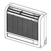
EMBEDDED INDOOR UNIT SETTING
(MUST BE PERFORMED)
• When embedding the indoor unit in a wall, restrict
the movement of the horizontal vane for the upper air
outlet so that it only operates horizontally.
•
If this setting is not performed, heat will build up in the
wall and the room will not be cooled or warmed properly.
• Cut the wires on the left and right sides of JRFBL
using a pair of nippers, etc., as shown here.
Cut the JRFBL wires.
Control board
JRFBL
JR24
Cut the wires on both ends.
Cut
• Use a grating with vertical bars, etc., that has at least 75 % open area. If the grating has horizontal bars or if the open
area is less than 75%, performance could be reduced.
• When the indoor unit is embedded in a wall (built-in), the time it takes for the room temperature to reach the set tem-
perature will increase
1-1/32(26)
18-11/16(475)
2-9/16(65)
23-5/8(600)
9/16(14)
2-9/16(65)
2-3/8(60)
31/32-1-3/8
(20-35)
3/8-25/32(10-20)
3/8-25/32(10-20)
3-11/32(85)
5-1/8
(130)
15-5/32(385)
2-1/16(52)
Lower air outlet
Receiver
Grating
Indoor unit
Backboard
Partition board
Upper air outlet
Partition board
Backboard
Partition board
Indoor temperatur
thermistor
3-15/16(100)
or more
3-15/16(100)
or more
3-15/16(100) or more
inch(mm)
(
10
) EMBEDDING THE INDOOR UNIT IN A WALL
 Loading...
