Do you have a question about the Mitsubishi Mr.Slim MFZ-KA09NA and is the answer not in the manual?
| Brand | Mitsubishi |
|---|---|
| Model | Mr.Slim MFZ-KA09NA |
| Category | Air Conditioner |
| Language | English |
Details the introduction of a new model for the specified series.
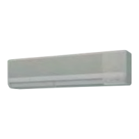
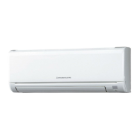
Visual identification and labeling of the indoor unit's external parts.
Identifies the specific indoor unit models covered by this manual.
Details the permissible operating conditions for temperature and humidity.
Specifies airflow performance characteristics like speed and coverage area.
Allows shortening the time for compressor start operation for service.
Procedures to modify P.C. boards for individual indoor unit operation.
Functionality for automatic unit restart after power failure.
Details the operation sequence and settings for cooling mode.
Details the operation sequence and settings for dry mode.
Details the operation sequence and settings for heating mode.
Explains automatic switching between COOL and HEAT modes.
Describes the automatic control and settings for the horizontal vane.
Instructions for setting and using the timer functions.
Customization of operation settings for specific modes.
Procedures for test runs and emergency operation modes.
How to switch temperature display between Fahrenheit and Celsius.
Important safety and procedural guidelines before starting troubleshooting.
Method to recall and diagnose past operational failures.
Step-by-step guides for diagnosing specific operational issues.
A table correlating operation indicator lamp patterns with symptoms and countermeasures.
Criteria for checking the condition of key internal components.
Specific diagnostic steps for indoor fan motor malfunctions.
Procedures to check remote controller, PC boards, and related components.
Diagnostic steps for miswiring and serial signal errors between units.
Procedures for diagnosing issues with the air outlet damper.
Guidance on identifying and resolving electromagnetic noise interference.
Provides test points and voltage references for the control board.
Step-by-step guide to removing the front panel of the indoor unit.
Instructions for safely removing the main electronic control board.
Procedure for detaching the unit's electrical box assembly.
Steps to remove the horizontal vane motor unit.
Guide for disassembling and removing the upper indoor fan motor.
Instructions for removing damper lock motors, damper motor, and limit switches.
Guide for disassembling and removing the lower indoor fan motor.