62
MXZ MICROPROCESSOR CONTROL
4
4-1. INVERTER SYSTEM CONTROL
4-1-1. MXZ-2A52VA
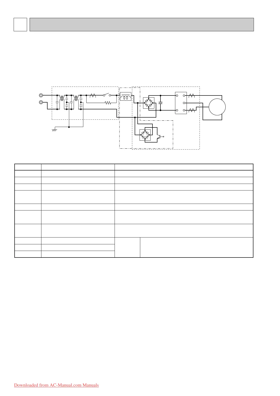
4-1-1-1. Inverter main power supply circuit
POWER P.C. BOARD
Power
supply
INVERTER P.C. BOARD
R64A R64B
CT61
TR821
DB65
X64
L61 L62
C63A
C63B
C63C
DB61
L64
P
W
V
U
N
CT761
CT781
IPM
U
W
MC
V
+
Booster chopper circucuit
SYMBOL
IPM
C63A/C63B/C63C
CT761/CT781
CT61
DB61
R64A, R64B
X64
DB65
TR821
L64
NAME
INTELLIGENT POWER MODULE
SMOOTHING CAPACITOR
CURRENT TRANSFORMER
CURRENT TRANSFORMER
DIODE MODULE
CURRENT-LIMITING RESISTOR
RELAY
DIODE MODULE
SWITCHING POWER TRANSISTOR
REACTOR
FUNCTION
It supplies three-phase AC power to compressor.
It stabilizes the DC voltage.
It measures the current of the compressor motor.
It measures the value of current which is supplied to the main power
supply circuit.
It converts the AC voltage to DC voltage.
It absorbs the rush current not to run into the main power supply circuit
when the electricity turns ON.
It short-circuits the resistance which restricts rush current during the
normal operation after the compressor startup.
Booster
chopper
circuit
Function of main parts
It improves power factor.
It rectifies AC and controls its voltage.
4-1-1-2. Outline of main power supply circuit
1. At the start of operation
Main power supply circuit is formed when X64 (Relay) is turned ON at compressor startup.
To prevent rush current from running into the circuit when power supply is turned ON,
R64A and R64B (Current-limitting resistor) are placed in sub circuit.
2. At normal operation
1 When AC runs into POWER P.C. board, its external noise is eliminated in the noise filter circuit.
2 After noise is eliminated from AC, it is rectified to DC by DB61 (Diode module).
3 DC voltage, to which AC has been rectified by process 2, is stabilized by C63A, C63B and C63C (Smoothing capacitor)
and supplied to IPM (Intelligent power module).
4 DC voltage, which has been stabilized in process 3, is converted to three-phase AC by IPM and supplied to
compressor.
5 CT761 and CT781 (Current Transformer), which are placed in the power supply circuit to compressor, are used to
measure the value of phase current and locate the polar direction of rotor with algorithm. PWM (Pulse width modulation)
controls impressed voltage and frequency with those information.
3. Purpose of PAM adoption
PAM : Pulse Amplitude Modulation
PAM has been adopted for the efficiency improvement and the adaptation to IEC harmonic current emission standard.
MXZ-2A52VA MXZ-4A71VA
MXZ-3A54VA MXZ-4A80VA
OBT14A--3qxp 06.1.12 1:10 PM Page 62
Downloaded from AC-Manual.com Manuals

 Loading...