147
OPERATING PROCEDURE
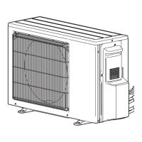
1. Removing the service panel and top panel
(1) Remove 3 service panel fixing screws (5 × 12) and slide
the hook on the right downward to remove the service
panel.
(2) Remove screws (3 for front, 3 for rear/5 × 12) of the top
panel and remove it.
2. Removing the fan motor (MF1, MF2)
(1) Remove the service panel. (See Figure 1)
(2) Remove the top panel. (See Figure 1)
(3) Remove 4 fan grille fixing screws (5 × 12) to detach the
fan grille. (See Figure 1)
(4) Remove a nut (for right handed screw of M6) to detach
the propeller. (See Photo 1.)
(5) Disconnect the connectors, CNF1 and CNF2 on multi con-
troller circuit board in electrical parts box.
(6) Remove 4 fan motor fixing screws (5 × 20) to detach the
fan motor. (See Photo 2)
Note1: Tighten the propeller fan with a torque of 5.7 i 0.3 N·m
[4.2 i 0.2 ft = lbs]
Photo 3
3. Removing the electrical parts box
(1) Remove the service panel. (See Figure 1)
(2) Remove the top panel. (See Figure 1)
(3) Disconnect the connecting wire from terminal block.
(4)
Remove all the following connectors from multi controller circuit board;
<Diagram symbol in the connector housing>
• Fan motor (CNF1, CNF2)
• Thermistor <HIC pipe> (TH2)
• Thermistor <Outdoor liquid pipe> (TH3)
•
Thermistor <Compressor> (TH4)
• Thermistor <Suction pipe/Ambient, Outdoor>
(TH7/6)
• High pressure switch (63H)
• High pressure sensor (63HS)
• Low pressure sensor (63LS)
• 4-way valve (21S4)
• Bypass valve (SV1)
• Electronic expansion valve (LEV-A, LEV-B)
Pull out the disconnected wire from the electrical parts box.
(5) Remove the terminal cover and disconnect the compressor
lead wire from the comp. terminal. (See Figure 2.)
Note: The terminal cover can be easily removed by using a
blade of flathead screwdriver.
Figure 1
MXZ-8C48NA MXZ-8C48NA-U1
Electrical parts box
Terminal block
(TB1)
Noise filter
circuit board (NF)
Terminal cover
Cover panel
(Front)
Cover panel
fixing screws
Compressor
(MC)
Valve bed
Valve bed
fixing screws
Side panel
(R)
Terminal block
(TB1B)
Multi controller
board (MULTI.B)
Terminal block
(TB3) (TB7)
Photo 1
Propeller Front panel
Nut
Photo 2
Top panel fixing screws
Top panel
Service panel
fixing screws
Service
panel
Fan grille
Grille fixing
screws
Grille fixing
screws
Slide
Service panel
fixing screw
Front panel fixing
screws (5x12)
Front
panel
fixing
screws
(4x10)
Front panel
fixing screws (5x12)
Note: Turn OFF the power supply before disassembly.
Continue to the next page
Fan motor fixing screws
Fan
motor
Fan motor fixing screws
 Loading...