EasyManua.ls Logo

Mitsubishi MXZ-8C60NA-U1 User Manual

Mitsubishi MXZ-8C60NA-U1
162 pages
To Next Page IconTo Next Page
Page #1 background imageLoading...
Page #1 background image
TECHNICAL & SERVICE MANUAL
CONTENTS
TECHNICAL CHANGES
.........................................
2
1. SAFETY PRECAUTION
....................................
3
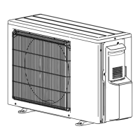
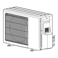
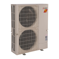
2. OVERVIEW OF UNITS
......................................
6
3. SPECIFICATIONS
............................................
10
4. DATA
................................................................
14
5. OUTLINES AND DIMENSIONS
......................
36
6. WIRING DIAGRAM
.........................................
40
7.
NECESSARY CONDITIONS FOR SYSTEM CONSTRUCTION
....
47
8. TROUBLESHOOTING
....................................
52
9.
PRECAUTIONS AGAINST REFRIGERANT LEAKAGE
....
140
10. DISASSEMBLY PROCEDURE
......................
141
No. OCH573
REVISED EDITION-C
MXZ-4C36NAHZ MXZ-4C36NAHZ-U1
MXZ-5C42NAHZ MXZ-5C42NAHZ-U1
MXZ-8C48NAHZ MXZ-8C48NAHZ-U1
MXZ-8C48NA MXZ-8C48NA-U1
MXZ-8C60NA-U1
PAC-MKA50BC
PAC-MKA30BC
PAC-MKA51BC
PAC-MKA31BC
HFC
utilized
R410A
October 2016
Notes:
• This service manual
describes technical data of
outdoor unit and branch box.
As for indoor units, refer to
its service manual.
RoHS compliant products
have <G> mark on the spec
name plate.
[Model Name]
<Outdoor unit>
MXZ-4C36NAHZ
MXZ-5C42NAHZ
MXZ-8C48NAHZ
MXZ-8C48NA
MXZ-8C60NA
<Branch box>
PAC-MKA50BC
PAC-MKA30BC
PAC-MKA51BC
PAC-MKA31BC
PARTS CATALOG (OCB573)
[Service Ref.]
OUTDOOR UNIT: MXZ-4C36NAHZ
BRANCH BOX: PAC-MKA51BC
Model name
indication
SPLIT-TYPE, HEAT PUMP AIR CONDITIONERS
Revision:
Added PAC-MKA51BC,
PAC-MKA31BC,
MXZ-4C36NAHZ-U1,
MXZ-5C42NAHZ-U1,
MXZ-8C48NAHZ-U1,
MXZ-8C48NA-U1, and
MXZ-8C60NA-U1 in REVISED
EDITION-C.
Some descriptions have been
modified.
OCH573 REVISED EDITION-B
is void.

Questions and Answers:

Mitsubishi MXZ-8C60NA-U1 Specifications

General IconGeneral
SeriesMXZ
Cooling Capacity60, 000 BTU/h
RefrigerantR410A
Voltage208/230V
Phase1
Compressor TypeInverter
Maximum Number of Connectable Indoor Units8
Indoor Unit Dimensions (H x W x D)Varies by model
Operating Temperature (Cooling)14°F to 115°F
Operating Temperature (Heating)-13°F to 75°F
Indoor Unit TypeVarious Types
Noise Level (Indoor Unit)Varies by model
Sound Level (dB)Varies by model

Summary

TECHNICAL CHANGES

SAFETY PRECAUTION

1-1. ALWAYS OBSERVE FOR SAFETY

General safety rules for operation.

1-2. CAUTIONS RELATED TO NEW REFRIGERANT

Specific cautions for units using refrigerant R410A.

1-3. Cautions for refrigerant piping work

Precautions for refrigerant piping with R410A.

SPECIFICATIONS

3-1. OUTDOOR UNIT:

Detailed specifications for various outdoor unit models.

3-2. BRANCH BOX:

Specifications for different branch box models.

NECESSARY CONDITIONS FOR SYSTEM CONSTRUCTION

7-2. REFRIGERANT SYSTEM DIAGRAM

Diagrams illustrating the refrigerant circuit for different models.

TROUBLESHOOTING

8-1. TROUBLESHOOTING

Overview of troubleshooting based on unit conditions and check codes.

8-2-4. Countermeasures for Error During Test Run

Lists common errors during test run and their countermeasures.

8-3. SELF-DIAGNOSIS ACTION BY FLOWCHART

Flowcharts for diagnosing specific errors like serial communication.

8-4. TROUBLESHOOTING BY INFERIOR PHENOMENA

Lists phenomena and their corresponding countermeasures.

PRECAUTIONS AGAINST REFRIGERANT LEAKAGE

9-1. PRECAUTIONS AGAINST REFRIGERANT LEAKAGE

General precautions regarding refrigerant leakage.

DISASSEMBLY PROCEDURE

Related product manuals