EasyManua.ls Logo

Mitsubishi MUZ-D30NA User Manual

Mitsubishi MUZ-D30NA
44 pages
To Next Page IconTo Next Page
Page #1 background imageLoading...
Page #1 background image
SERVICE MANUAL
CONTENTS
1. TECHNICAL CHANGES ··································· 3
2. PART NAMES AND FUNCTIONS ····················· 3
3. SPECIFICATION ················································ 4
4. OUTLINES AND DIMENSIONS ························ 6
5. WIRING DIAGRAM ············································ 7
6. REFRIGERANT SYSTEM DIAGRAM ··············11
7. DATA ································································ 13
8. ACTUATOR CONTROL ··································· 20
9. SERVICE FUNCTIONS ··································· 21
10. TROUBLESHOOTING ····································· 22
11. DISASSEMBLY INSTRUCTIONS ···················· 41
Models
MUZ-D30NA / -
1
/ -
U1
/ -
U2
MUZ-D36NA / -
1
/ -
U1
/ -
U2
MUY-D30NA / -
1
MUY-D36NA / -
1
SPLIT-TYPE AIR CONDITIONERS
OUTDOOR UNIT
Indoor unit service manual
MSZ-D•NA Series (OBH501)
MSY-D•NA Series (OBH501)
NOTE:
RoHS compliant products have <G> mark on the spec name plate.
TM
HFC
utilized
R410A
No. OBH502
REVISED EDITION-C
PARTS CATALOG (OBB502)
Revision C:
Errors in TROUBLESHOOTING have been
corrected.
Please void OBH502 REVISED EDITION-B.
Question and Answer IconNeed help?

Do you have a question about the Mitsubishi MUZ-D30NA and is the answer not in the manual?

Mitsubishi MUZ-D30NA Specifications

General IconGeneral
BrandMitsubishi
ModelMUZ-D30NA
CategoryAir Conditioner
LanguageEnglish

Summary

TECHNICAL CHANGES

PART NAMES AND FUNCTIONS

SPECIFICATION

OUTLINES AND DIMENSIONS

WIRING DIAGRAM

REFRIGERANT SYSTEM DIAGRAM

DATA

MAX. REFRIGERANT PIPING LENGTH and MAX. HEIGHT DIFFERENCE

Specifies maximum refrigerant piping length and height difference.

ADDITIONAL REFRIGERANT CHARGE (R410A: oz.)

Details additional refrigerant charge calculation for extended piping.

PERFORMANCE DATA

Provides performance data including cooling and heating capacities.

PERFORMANCE CURVE

Graphical representation of performance characteristics under various conditions.

CONDENSING PRESSURE

Data on condensing pressure based on indoor/outdoor conditions.

STANDARD OPERATION DATA

Key operational data for standard conditions.

CAPACITY AND INPUT CORRECTION BY INVERTER OUTPUT FREQUENCY

Correction factors for capacity and input based on compressor frequency.

TEST RUN OPERATION (How to operate fixed-frequency operation)

Procedure for conducting test run operation with fixed frequency.

ACTUATOR CONTROL

OUTDOOR FAN MOTOR CONTROL

Control logic for the outdoor fan motor based on compressor operation.

R.V. COIL CONTROL

Control operation of the reversing valve coil for heating and cooling modes.

Relation between main sensor and actuator

Maps sensors to actuators for system control and protection.

SERVICE FUNCTIONS

PRE-HEAT CONTROL

Function to prevent compressor damage from moisture by heating the winding.

CHANGE IN DEFROST SETTING

Procedure to adjust the defrost finish temperature setting.

TROUBLESHOOTING

CAUTIONS ON TROUBLESHOOTING

Important safety and handling precautions before troubleshooting.

FAILURE MODE RECALL FUNCTION

How to recall and analyze past failure modes for diagnosis.

TROUBLESHOOTING CHECK TABLE

Table listing symptoms, indications, conditions, and remedies for troubleshooting.

TROUBLE CRITERION OF MAIN PARTS

Criteria for checking the functionality of major components.

TROUBLESHOOTING FLOWS

Step-by-step diagnostic guides for various components.

Electromagnetic Noise Issues

Guidelines for addressing electromagnetic noise interference with electronic devices.

DISASSEMBLY INSTRUCTIONS

Removing the cabinet

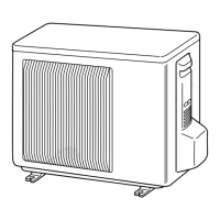
Step-by-step guide to remove the outdoor unit cabinet components.

Removing the inverter assembly, P.C. board and power board

Instructions for removing internal electronic boards and assemblies.

Removing R.V. coil (MUZ)

Procedure for removing the Reversing Valve coil component.

Removing Thermistors and Sensors

Steps to remove temperature sensors from the outdoor unit.

Removing outdoor fan motor

Guide for disassembling and removing the outdoor fan motor.

Removing the compressor and 4-way valve

Process for removing the compressor and 4-way valve assembly.

Removing the reactor

Instructions for removing the reactor component.
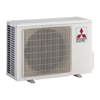
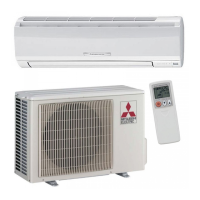
Related product manuals