EasyManua.ls Logo

Mitsubishi MUH-GA50VB User Manual

Mitsubishi MUH-GA50VB
52 pages
To Next Page IconTo Next Page
Page #1 background imageLoading...
Page #1 background image
SERVICE MANUAL
CONTENTS
1. TECHNICAL CHANGES ····································2
2. PART NAMES AND FUNCTIONS······················5
3. SPECIFICATION·················································6
4. NOISE CRITERIA CURVES·······························8
5. OUTLINES AND DIMENSIONS ·························9
6. WIRING DIAGRAM ··········································10
7. REFRIGERANT SYSTEM DIAGRAM ··············12
8. PERFORMANCE CURVES······························15
9. SERVICE FUNCTIONS ····································25
10. TROUBLESHOOTING······································25
11. DISASSEMBLY INSTRUCTIONS·····················36
12. PARTS LIST······················································40
13. RoHS PARTS LIST···········································46
Models
MUH-GA50VB -
MUH-GA50VB -
MUH-GA60VB -
MUH-GA80VB -
E1
E1
E2
E1
SPLIT-TYPE AIR CONDITIONERS
MUH-GA50VB
NOTE:
This service manual describes technical data of outdoor units.
RoHS compliant products have <G> mark on the spec name plate.
For servicing of RoHS compliant products, refer to the RoHS Parts List.
HFC
utilized
R410A
OUTDOOR UNIT
No. OB368
REVISED EDITION-C
Please void OB368 REVISED EDITION-B.
Revision:C
• The fan guard for MUH-GA60VB- and
MUH-GA80VB- has been changed.
E1
E1
Indoor unit service manual
MSH-GAVB Series (OB367)
OB368B-1.qxp 10.5.25 9:14 AM Page 1
Question and Answer IconNeed help?

Do you have a question about the Mitsubishi MUH-GA50VB and is the answer not in the manual?

Mitsubishi MUH-GA50VB Specifications

General IconGeneral
TypeSplit System
Cooling Capacity5.0 kW
Power Supply220-240V, 50Hz
RefrigerantR410A
Seasonal Energy Efficiency Ratio (SEER)6.10

Summary

OUTDOOR UNIT SERVICE MANUAL

Models

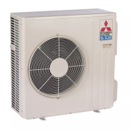
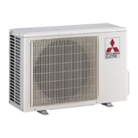
Lists the specific outdoor unit models covered by this service manual.

INFORMATION FOR THE AIR CONDITIONER WITH R410A REFRIGERANT

1 TECHNICAL CHANGES

Details modifications and improvements made to the outdoor units.

2 PART NAMES AND FUNCTIONS

3 SPECIFICATION

5 OUTLINES AND DIMENSIONS

6 WIRING DIAGRAM

7 REFRIGERANT SYSTEM DIAGRAM

MAX. REFRIGERANT PIPING LENGTH

ADDITIONAL REFRIGERANT CHARGE(R410A : g)

Tables for calculating the additional refrigerant charge based on piping length.

8 PERFORMANCE CURVES

OUTDOOR LOW PRESSURE AND OUTDOOR UNIT CURRENT COOL operation

PERFORMANCE DATA COOL operation

PERFORMANCE DATA HEAT operation

9 SERVICE FUNCTIONS

Service Functions and Settings

Details on service functions and how to change defrost settings.

10 TROUBLESHOOTING

10-1. CAUTIONS ON TROUBLESHOOTING

Important safety precautions and checks before troubleshooting.

10-2. INSTRUCTION OF TROUBLESHOOTING

10-3. TROUBLE CRITERION OF MAIN PARTS

10-4. TROUBLESHOOTING FLOW

Check of outdoor unit

Diagnostic flowchart for outdoor unit operational issues.

When OPERATION INDICATOR lamp flashes 10-time.

Check of LEV (Expansion valve)

Troubleshooting procedure for the expansion valve when indicator flashes 10 times.

When OPERATION INDICATOR lamp flashes 6-time.

Check of outdoor thermistor

Troubleshooting procedure for abnormal outdoor thermistors.
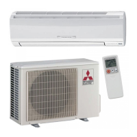
10-5. TEST POINT DIAGRAM AND VOLTAGE

11 DISASSEMBLY INSTRUCTIONS

12 PARTS LIST (non-RoHS compliant)

PARTS LIST (non-RoHS compliant)

13 RoHS PARTS LIST (RoHS compliant)

RoHS PARTS LIST (RoHS compliant)

Related product manuals