25
SERVICE FUNCTIONS
9
9-1. COMPULSORY DEFROSTING MODE FOR SERVICE
By short circuit of the connector JPDS and JPSG(MUH-GA50VB)/ JPG1 and R871(MUH-GA60/GA80VB) on the outdoor
deicer P.C. board, defrosting mode can be accomplished regardless of the defrost interval restriction. (Refer to 10-5.)
Defrost thermistor RT61 must read below -3°C.
9-2. CHANGE IN DEFROST SETTING
<JRF> When the JRF wire of the deicer P.C. board is cut, the defrost interval time will be changed.
<JRG> When the JRG wire of the deicer P.C. board is cut, the defrost temperature will be changed.
(Refer to 10-5.)
Jumper wire
JRF
JRG
Model Change point
Defrost interval time changes from 40 minutes to 15 minutes.
Defrost start temperature changes from -3: to 0:. (MUH-GA50VB)
Defrost start temperature does not change.(-3.0:)(MUH-GA60/GA80VB)
Defrost finish temperature changes from 3: to 10:.(MUH-GA50VB)
Defrost finish temperature changes from 3: to 15:.(MUH-GA60VB)
Defrost finish temperature changes from 13: to 15:.(MUH-GA80VB)
MUH-GA50VB
MUH-GA60VB
MUH-GA80VB
MUH-GA50VB MUH-GA60VB MUH-GA80VB
TROUBLESHOOTING
10
10-1. CAUTIONS ON TROUBLESHOOTING
1. Before troubleshooting, check the following:
(1) Check the power supply voltage.
(2) Check the indoor/outdoor connecting wire for mis-wiring.
2. Take care the following during servicing.
(1) Before servicing the air conditioner, be sure to turn OFF the main unit first with the remote controller, and then after con-
firming the horizontal vane is closed, turn OFF the breaker and / or disconnect the power plug.
(2) Be sure to turn OFF the power supply before removing the front panel, the cabinet, the top panel, and the electronic
control P.C. board.
(3) When removing the electronic control P.C. board, hold the edge of the board with care NOT to apply stress on the com-
ponents.
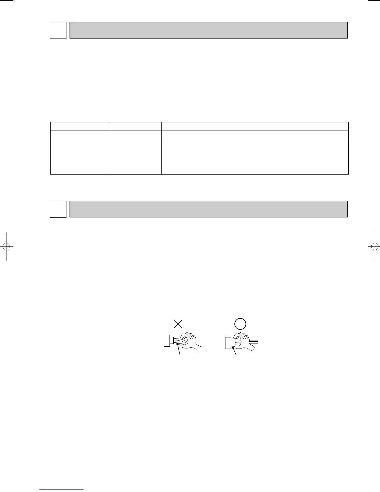
(4) When connecting or disconnecting the connectors, hold the housing of the connector. DO NOT pull the lead wires.
MUH-GA50VB MUH-GA60VB MUH-GA80VB
3. Troubleshooting procedure
(1) First, check if the OPERATION INDICATOR lamp on the indoor unit is flashing on and off to indicate an abnormality.
To make sure, check how many times the abnormality indication is flashing on and off before starting service work.
(2) Before servicing check that the connector and terminal are connected properly.
(3) If the electronic control P.C. board is supposed to be defective, check the copper foil pattern for disconnection and the
components for bursting and discolouration.
(4) When troubleshooting, refer to 10-2.
OB368B-1.qxp 10.5.25 9:14 AM Page 25
 Loading...