EasyManua.ls Logo

Mitsubishi MUZ-D36NA Service Manual

Mitsubishi MUZ-D36NA
44 pages
To Next Page IconTo Next Page
Page #1 background imageLoading...
Page #1 background image
SERVICE MANUAL
CONTENTS
1. TECHNICAL CHANGES ··································· 3
2. PART NAMES AND FUNCTIONS ····················· 3
3. SPECIFICATION ················································ 4
4. OUTLINES AND DIMENSIONS ························ 6
5. WIRING DIAGRAM ············································ 7
6. REFRIGERANT SYSTEM DIAGRAM ··············11
7. DATA ································································ 13
8. ACTUATOR CONTROL ··································· 20
9. SERVICE FUNCTIONS ··································· 21
10. TROUBLESHOOTING ····································· 22
11. DISASSEMBLY INSTRUCTIONS ···················· 41
Models
MUZ-D30NA / -
1
/ -
U1
/ -
U2
MUZ-D36NA / -
1
/ -
U1
/ -
U2
MUY-D30NA / -
1
MUY-D36NA / -
1
SPLIT-TYPE AIR CONDITIONERS
OUTDOOR UNIT
Indoor unit service manual
MSZ-D•NA Series (OBH501)
MSY-D•NA Series (OBH501)
NOTE:
RoHS compliant products have <G> mark on the spec name plate.
TM
HFC
utilized
R410A
No. OBH502
REVISED EDITION-C
PARTS CATALOG (OBB502)
Revision C:
Errors in TROUBLESHOOTING have been
corrected.
Please void OBH502 REVISED EDITION-B.
Question and Answer IconNeed help?

Do you have a question about the Mitsubishi MUZ-D36NA and is the answer not in the manual?

Mitsubishi MUZ-D36NA Specifications

General IconGeneral
BrandMitsubishi
ModelMUZ-D36NA
CategoryAir Conditioner
LanguageEnglish

Summary

TECHNICAL CHANGES

New Model Information

Details about new model introductions and specification changes.

PART NAMES AND FUNCTIONS

Outdoor Unit Components

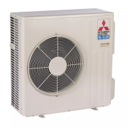
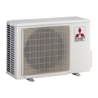
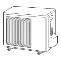
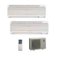
Identification of external parts of the outdoor unit.

SPECIFICATION

Technical Specifications Overview

Key operational and physical specifications for the models.

OUTLINES AND DIMENSIONS

Unit Dimensions and Required Space

Physical dimensions and installation space requirements.

WIRING DIAGRAM

Electrical Wiring Schematics

Circuit diagrams showing electrical connections for the unit.

REFRIGERANT SYSTEM DIAGRAM

Refrigerant Circuit Layout

Diagram illustrating the refrigerant flow and components.

MAX. REFRIGERANT PIPING LENGTH and MAX. HEIGHT DIFFERENCE

Piping Length and Height Limitations

Guidelines for refrigerant pipe length and height differences.

ADDITIONAL REFRIGERANT CHARGE (R410A: oz.)

Refrigerant Charge Calculation

Procedures for calculating additional refrigerant charge.

DATA

Performance Data Cooling Capacity

Tables detailing cooling capacity under various conditions.

Performance Curve Cooling

Graphical representation of cooling performance.

Condensing Pressure Cooling

Charts showing condensing pressure based on temperature.

Standard Operation Data

Summary of standard operational parameters.

ACTUATOR CONTROL

Outdoor Fan Motor Control Logic

How the outdoor fan motor operates with the compressor.

R.V. Coil Control Logic

Control logic for the reversing valve coil.

SERVICE FUNCTIONS

Pre-Heat Control Activation

Method to activate pre-heat control for compressor protection.

Changing Defrost Setting

Procedure to adjust the defrost finish temperature.

TROUBLESHOOTING

Cautions for Troubleshooting

Important safety and procedural notes before troubleshooting.

Failure Mode Recall Function

How to recall and interpret failure modes.

Troubleshooting Check Table

Comprehensive table of symptoms, conditions, and remedies.

Troubleshooting Flow Inverter/Compressor

Step-by-step guide for checking inverter and compressor issues.

Electromagnetic Noise Interference

Steps to identify and mitigate electromagnetic noise issues.

DISASSEMBLY INSTRUCTIONS

Removing the Cabinet

Step-by-step guide to removing the unit's cabinet.

Removing Inverter Assembly and Boards

Procedure for removing power, control, and filter boards.

Removing Compressor and 4-Way Valve

Instructions for removing the compressor and 4-way valve.

Related product manuals