Do you have a question about the Mitsubishi MU17NN and is the answer not in the manual?
Allows selection of five airflow settings to match room layout and people's location.
Sleek design of NW/NN Series matches virtually any room layout, featuring smaller dimensions than previous models.
Automatically restarts the equipment in the previous mode after a power outage.
Advanced design for powerful and energy-efficient operation, resulting in lower operating costs.
Details changes in indoor/outdoor units, remote controllers, and features for specific model series, including MS17NN.
Identifies and describes the functions of various sections of the wireless remote controller.
Details cooling capacity, power consumption, dimensions, weight, and airflow for indoor units.
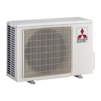
Details power supply, fuse size, fan motor, compressor, refrigerant, and dimensions for outdoor units.
Specifies maximum refrigerant pipe lengths and height differences between indoor and outdoor units.
Presents cooling capacity data based on indoor/outdoor temperatures and humidity conditions.
Provides correction factors for cooling capacity based on refrigerant piping length.
Graphical representation of cooling capacity and power consumption versus operating temperatures.
Displays pressure curves for outdoor units based on ambient and indoor temperatures.
Details electrical specifications, refrigerant pressures, temperatures, and charge for unit operation.
Lists operating conditions like intake air temperature, discharge air temperature, and fan speed.
Defines power supply requirements, guaranteed voltage, and operational temperature/humidity ranges.
Provides data on airflow rate, air speed, and coverage range for different models.
Specifies additional refrigerant charge requirements based on piping length.
Diagrams and measurements for MS09NW indoor and MU09NW outdoor units, including installation space.
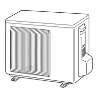
Diagrams and measurements for MS12/15/17NN indoor and MU12/15/17NN outdoor units.
Illustrates the electrical connections for MS09NW indoor and MU09NW outdoor units.
Illustrates electrical connections for MS12/15/17NN indoor and MU12/15/17NN outdoor units.
Diagrams showing refrigerant flow and components for MS09/12/15/17NW and MU09/12/15/17NN units.
Details how to use the 'I FEEL CONTROL' feature via the remote controller for temperature adjustment.
Explains initial set temperature determination and function of TOO WARM/COOL buttons.
Explains compressor, fan operation, coil frost prevention, and humidity control in COOL and DRY modes.
Step-by-step guides for operating in COOL and DRY modes, including a DRY mode temperature chart.
Details vane positioning logic, automatic angle determination, dew prevention, and SWING mode.
Step-by-step guide for setting, canceling, and combining ON/OFF timers.
Instructions for operating the unit using the emergency switch when the remote is unavailable.
Explains auto restart function and how to shorten timer delay times for service.
Details how to modify PC boards for individual operation of multiple indoor units.
Provides essential precautions, safety tips, and general procedures before starting troubleshooting.
Instructions on how to properly replace batteries in the remote controller and perform a reset.
A flowchart and table for diagnosing issues based on symptoms, indicator lamps, and repair actions.
Details resistance and voltage checks for main components like thermistors, motors, and compressors.
Step-by-step guide to diagnose and troubleshoot indoor fan motor operation issues.
Procedure to diagnose issues with the remote controller receiver and related boards.
Guide to diagnose problems with the indoor unit's main electronic control board.
Troubleshooting steps for the compressor and outdoor fan when they do not operate.
Detailed diagram showing test points and voltage measurements on the MS09NW indoor P.C. board.
Diagrams for test points and voltage measurements on MS12/15/17NN indoor P.C. boards.
Procedure for removing the front panel and electronic control/display P.C. boards of the MS09NW indoor unit.
Instructions for removing the electrical box, vane motor, line flow fan, and indoor fan motor.
Procedure for removing the front panel and electronic P.C. board of MS12/15/17NN indoor units.
Instructions for removing the indoor fan, line flow fan, and nozzle assembly from indoor units.
Procedure for removing the cabinet, propeller fan, and outdoor fan motor of the MU09NW outdoor unit.
Procedure for removing the compressor, including electrical connections and refrigerant release.
Procedure for removing the cabinet and electrical parts like capacitors from outdoor units.
Instructions for removing the outdoor fan motor and compressor from outdoor units.
List and diagrams of structural and heat exchanger components for the MS09NW indoor unit.
List of electrical components for the MS09NW indoor unit.
List and diagrams of structural components for the MU09NW outdoor unit.
List of functional and electrical components for the MU09NW outdoor unit.
List of structural and heat exchanger components for MS12/15/17NN indoor units.
List of electrical components for MS12/15/17NN indoor units.
List of structural components for MU12/15/17NN outdoor units.
Lists remote controller and holder parts for the air conditioning system.
Details optional refrigerant pipe kits, lengths, sizes, and additional charge requirements.
Information on the function, life, cleaning, and replacement of air cleaning and deodorizing filters.
| Brand | Mitsubishi |
|---|---|
| Model | MU17NN |
| Category | Air Conditioner |
| Language | English |