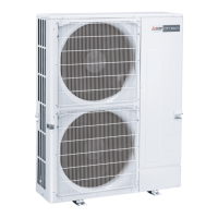
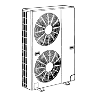
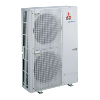
Do you have a question about the Mitsubishi PUG18AYB and is the answer not in the manual?
Performance data and operating pressures for PK18+PUG18.
Performance data and operating pressures for PK24+PUG24.
Performance data and operating pressures for PK30+PUG30.
Performance data and operating pressures for PK36+PUG36.
Performance data and operating pressures for PL18+PUG18.
Performance data and operating pressures for PL24+PUG24.
Performance data and operating pressures for PL30+PUG30.
Performance data and operating pressures for PL36+PUG36.
Performance data and operating pressures for PL42+PUG42.
Performance data and operating pressures for PC24+PUG24.
Performance data and operating pressures for PC30+PUG30.
Performance data and operating pressures for PC36+PUG36.
Performance data and operating pressures for PC42+PUG42.
Information on determining and verifying the total system refrigerant charge.
Table for determining required suction tube temperature based on pressure.
Describes how outdoor unit operation is activated by the indoor unit.
Explains P8 fault code and its causes related to indoor coil temperature.
Schematic illustrating electrical connections for the unit components.
| Brand | Mitsubishi |
|---|---|
| Model | PUG18AYB |
| Category | Air Conditioner |
| Language | English |


