EasyManua.ls Logo

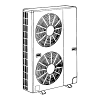
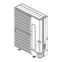
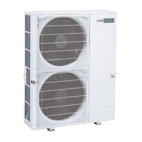
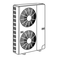
Mitsubishi PUMY-P100YHM User Manual

Mitsubishi PUMY-P100YHM
94 pages
To Next Page IconTo Next Page
Page #1 background imageLoading...
Page #1 background image
TECHNICAL & SERVICE MANUAL
SPLIT-TYPE, HEAT PUMP AIR CONDITIONERS
CONTENTS
1. TECHNICAL CHANGES
...................................
2
2. SAFETY PRECAUTION
....................................
2
3. OVERVIEW OF UNITS
......................................
5
4. SPECIFICATIONS
.............................................
7
5. DATA
.................................................................
8
6. OUTLINES AND DIMENSIONS
......................
18
7. WIRING DIAGRAM
.........................................
20
8.
NECESSARY CONDITIONS FOR SYSTEM CONSTRUCTION
.....
22
9. TROUBLESHOOTING
....................................
32
10. ELECTRICAL WIRING
....................................
74
11. REFRIGERANT PIPING TASKS
.....................
77
12. DISASSEMBLY PROCEDURE
.......................
81
13. PARTS LIST
.....................................................
87
14. RoHS PARTS LIST
..........................................
90
15. OPTIONAL PARTS
..........................................
93
OUTDOOR UNIT
No. OC355
REVISED EDITION-D
[Service Ref.]
PUMY-P100YHM
PUMY-P100YHM1
PUMY-P100YHMA
PUMY-P125YHM
PUMY-P125YHM1
PUMY-P125YHMA
PUMY-P140YHM
PUMY-P140YHM1
PUMY-P140YHMA
PUMY-P100YHMA-BS
PUMY-P125YHMA-BS
PUMY-P140YHMA-BS
HFC
utilized
R410A
June 2008
NOTE :
· This service manual describes technical data of outdoor unit.
As for indoor units, refer to its service manual.
· RoHS compliant products have <G> mark on spec name plate.
· For servicing of RoHS compliant products, refer to RoHS PARTS LIST.
[Model name]
<Outdoor unit>
PUMY-P100YHM
PUMY-P100YHMA
PUMY-P125YHM
PUMY-P125YHMA
PUMY-P140YHM
PUMY-P140YHMA
PUMY-P100YHMA-BS
PUMY-P125YHMA-BS
PUMY-P140YHMA-BS
• Please void OC355
REVISED EDITION-C.
Model name
indication
Revision:
PUMY-P100/125/140YHMA-BS
are added in
REVISED EDITION-D.
Some descriptions have
been modified.
Question and Answer IconNeed help?

Do you have a question about the Mitsubishi PUMY-P100YHM and is the answer not in the manual?

Mitsubishi PUMY-P100YHM Specifications

General IconGeneral
BrandMitsubishi
ModelPUMY-P100YHM
CategoryAir Conditioner
LanguageEnglish

Summary

Mitsubishi Electric Technical Changes for PUMY Series

Safety Precautions for R410A Refrigerant and Service

R410A Refrigerant Safety Precautions

Essential safety measures and guidelines for using R410A refrigerant.

Service & Maintenance Safety Guidelines

Important safety notes for performing service and maintenance tasks.

Refrigerant Charging Procedures

Correct methods for adding refrigerant, including cylinder handling.

Recommended Tools for R410A Refrigerant

List of specialized tools required for R410A refrigerant work.

Salt Proof (-BS) Model Installation Precautions

Specific installation guidelines to maintain salt resistance for -BS models.

Refrigerant Piping Work and Tool Guidelines

R410A Refrigerant Piping Work Guidelines

Precautions for refrigerant piping, including pipe thickness and flare dimensions.

Tools & Materials Compatibility for R410A

Table indicating which conventional tools can be used with R410A.

3 OVERVIEW OF UNITS

Unit Construction and System Configurations

Details on outdoor unit capacities and connectable indoor unit types.

3-2. UNIT SPECIFICATIONS

Outdoor Unit Technical Specifications

Key performance and electrical data for outdoor units.

MULTI-S Model Identification Guide

How to identify indoor and outdoor unit models using their codes.

Unit Operating Temperature Limits

Defines the acceptable indoor and outdoor temperature ranges for operation.

4 SPECIFICATIONS

5 DATA

5-1. COOLING AND HEATING CAPACITY CHARACTERISTICS

Procedures for determining system cooling and heating capacities.

5-1-1. System Capacity Calculation Method

Steps to determine total system cooling and heating capacity.

5-1-2. Indoor Unit Capacity Calculation Method

How to calculate capacity for each indoor unit within a system.

5-2. STANDARD CAPACITY DIAGRAM

Standard Capacity Data for PUMY-P100/125/140YHM

Tables showing capacity and power consumption based on total indoor unit capacity.

5-2. STANDARD CAPACITY DIAGRAM

5-2. STANDARD CAPACITY DIAGRAM

5-2. STANDARD CAPACITY DIAGRAM

5-2. STANDARD CAPACITY DIAGRAM

5-2. STANDARD CAPACITY DIAGRAM

5-3. CORRECTING COOLING AND HEATING CAPACITY

5-3-1. Correcting Changes in Air Conditions

How air conditions affect capacity and how to correct it.

Capacity Correction Factor Curves

Graphical data for adjusting capacity based on temperature conditions.

5-3. CORRECTING COOLING AND HEATING CAPACITY

5-3-2. Correcting Capacity for Refrigerant Piping Length

How refrigerant piping length affects capacity and correction methods.

5-3-3. Heating Capacity Correction for Frost/Defrosting

Correction factors for heating capacity during frost or defrost conditions.

5-4. NOISE CRITERION CURVES

6 OUTLINES AND DIMENSIONS

Installation Space Requirements

Recommended clearances for installation and service access.

Foundation and Piping/Wiring Access

Guidelines for unit installation and connection points.

Piping Knockout Hole Details

Dimensions and locations of holes for piping connections.

8 WIRING DIAGRAM

Outdoor Unit Wiring Diagram and Symbols

Schematic showing electrical connections and component symbols.

Service Precautions & Self-Diagnosis Function

Safety warnings during service and how to use the self-diagnosis feature.

8 NECESSARY CONDITIONS FOR SYSTEM CONSTRUCTION

8-1. TRANSMISSION SYSTEM SETUP

How to set up the transmission system, including wiring and address settings.

8-2. REFRIGERANT SYSTEM DIAGRAM

8-3. SYSTEM CONTROL

8-3-1. System Control Examples

Examples of wiring and address settings for M-NET remote control systems.

M-NET Remote Controller System Examples

Examples of standard, 2-controller, and group operations.

8-3. SYSTEM CONTROL

Remote Controller Connection Units & Limits

Max units, lengths, and prohibited connections for remote controllers.

8-3. SYSTEM CONTROL

M-NET Group Operation Wiring Diagram

Example of wiring for group operation with multiple outdoor units and M-NET controller.

8-3. SYSTEM CONTROL

MA Remote Controller System Configurations

Examples of wiring and address settings for MA remote controller systems.

8-3. SYSTEM CONTROL

MA Group Operation Wiring Diagram

Example of wiring for group operation with multiple outdoor units and MA controller.

9 TROUBLESHOOTING

9-1. CHECK POINTS FOR TEST RUN

Steps and checks required before and during system test runs.

9-1-1. Procedures of Test Run

Detailed steps for conducting the operational test run.

9-1-2. Special Function Operation and Settings (for M-NET Remote Controller)

(A) Group Settings Procedure

Steps for setting up group operation with indoor units.

(B) Paired Settings Procedure

Steps for setting up linked operation with Lossnay units.

9-1-2. Special Function Operation and Settings (for M-NET Remote Controller)

Address Check and Clearing

Procedures for checking and clearing unit addresses on the remote controller.

9-1-3. Countermeasures for Error During Test Run

Test Run Error Codes and Solutions

Troubleshooting guide for error codes detected during test runs.

Outdoor Unit Self-Diagnosis Function

How to use the self-diagnosis switch and LEDs for troubleshooting.

9-1-3. Countermeasures for Error During Test Run

9-1-3. Countermeasures for Error During Test Run

9-1-3. Countermeasures for Error During Test Run

9-1-3. Countermeasures for Error During Test Run

9-1-3. Countermeasures for Error During Test Run

9-1-3. Countermeasures for Error During Test Run

9-1-3. Countermeasures for Error During Test Run

9-1-3. Countermeasures for Error During Test Run

9-1-3. Countermeasures for Error During Test Run

9-1-3. Countermeasures for Error During Test Run

9-1-3. Countermeasures for Error During Test Run

9-1-3. Countermeasures for Error During Test Run

9-1-3. Countermeasures for Error During Test Run

9-1-3. Countermeasures for Error During Test Run

9-1-3. Countermeasures for Error During Test Run

9-1-3. Countermeasures for Error During Test Run

9-2. REMOTE CONTROLLER DIAGNOSIS

9-3. REMOTE CONTROLLER TROUBLE

M-NET Remote Controller Issues

Common symptoms and solutions for M-NET remote controller problems.

MA Remote Controller Issues

Common symptoms and solutions for MA remote controller problems.

9-4. NORMAL OPERATING SYMPTOMS (NOT TROUBLE)

9-5. INTERNAL SWITCH FUNCTION TABLE

9-5. INTERNAL SWITCH FUNCTION TABLE

9-6. OUTDOOR UNIT INPUT/OUTPUT CONNECTOR

Outdoor Unit Connector Functions

Description of connectors CN51, CN3N, and CN3D and their functions.

Silent Mode & Demand Control Settings

How to select silent mode and demand control using DIP switches.

9-7. HOW TO CHECK THE PARTS

DC Fan Motor & Outdoor Controller Circuit Board Check

9-8. HOW TO CHECK THE COMPONENTS

9-9. OUTDOOR UNIT FUNCTIONS

Outdoor Power Circuit Board Layout

Outdoor Converter Circuit Board Layout

Outdoor Noise Filter Circuit Board Layout

Transmission Power Board Layout

9-10. OUTDOOR UNIT FUNCTIONS

9-10. OUTDOOR UNIT FUNCTIONS

9-10. OUTDOOR UNIT FUNCTIONS

9-10. OUTDOOR UNIT FUNCTIONS

9-10. OUTDOOR UNIT FUNCTIONS

9-10. OUTDOOR UNIT FUNCTIONS

9-10. OUTDOOR UNIT FUNCTIONS

10 ELECTRICAL WIRING

10-1. OVERVIEW OF POWER WIRING

General principles and considerations for power wiring.

10-2. WIRE DIAMETER AND MAIN POWER SWITCH CAPACITY

Specifications for wire diameter and main power switch capacity.

10-2-1. Wiring Diagram for Main Power Supply

Schematic showing the wiring for the main power supply.

10-2-2. Power Supply Wire Diameter and Capacity

Table detailing wire diameter and capacity requirements.

10-3. DESIGN FOR CONTROL WIRING

10-3-1. Selection Number of Control Wires

Guidance on choosing the correct number of control wires.

10-3-2. Control Signal Wires

Details on transmission wire types and maximum lengths.

10-3-3. M-NET Remote Controller Wiring

Specifications for M-NET remote controller cable types and diameters.

10-3-4. MA Remote Control Cables

Specifications for MA remote controller cable types and diameters.

10-4. SYSTEM SWITCH SETTING

10-5. EXAMPLE EXTERNAL WIRING DIAGRAM FOR A BASIC SYSTEM

10-5-1. Example using a M-NET remote controller

A sample wiring diagram for a basic system with an M-NET controller.

10-6. METHOD FOR OBTAINING ELECTRICAL CHARACTERISTICS WHEN A CAPACITY AGREEMENT IS TO BE SIGNED WITH AN ELECTRIC POWER COMPANY

10-6-1. Obtaining Electrical Characteristics

Formulas for obtaining total power consumption, current, and power factor.

(1) Total Power Consumption Calculation

Procedure to determine the system's total power consumption.

(2) Total Current Calculation

Procedure to determine the system's total current.

(3) System Power Factor Calculation

Formula for calculating the system power factor.

10-6-2. Applying to Electric Power Company

11 REFRIGERANT PIPING TASKS

11-1. REFRIGERANT PIPING SYSTEM

Details on piping methods, branch kits, and diameters.

Selecting Refrigerant Branch Kits

Guidance on selecting the appropriate branch piping kits.

Additional Refrigerant Charge Calculation

Method to calculate extra refrigerant needed based on piping length.

11-2. PRECAUTIONS AGAINST REFRIGERANT LEAKAGE

11-2-1. Introduction to Refrigerant Leakage

Information on R410A toxicity and concentration limits in rooms.

11-2-2. Confirming R410A Concentration Procedure

Procedure to confirm R410A concentration and take appropriate action.

12 DISASSEMBLY PROCEDURE

1. Service Panel and Top Panel Removal

Instructions for removing the unit's access panels.

2. Fan Motor Removal (MF1, MF2)

Procedures for safely removing the fan motor components.

3. Electrical Parts Box Removal

Steps for removing the electrical components box.

12 DISASSEMBLY PROCEDURE

4. Thermistor <Low Pressure Saturated Temp.> (TH6) Removal

Procedure for removing the low pressure saturated temperature thermistor.

5. Thermistor <Outdoor> (TH7) Removal

Procedure for removing the outdoor temperature thermistor.

12 DISASSEMBLY PROCEDURE

6. Thermistor <Outdoor Pipe> (TH3) & <Discharge> (TH4) Removal

Steps for removing the outdoor pipe and discharge temperature thermistors.

7. 4-Way Valve Coil (21S4) Removal

Procedure for removing the 4-way valve coil.

8. 4-Way Valve Removal

Steps for removing the 4-way valve and its components.

12 DISASSEMBLY PROCEDURE

9. Bypass Valve Coil (SV1) & Bypass Valve Removal

Procedure for removing the bypass valve coil and valve.

10. High Pressure Switch (63H) & Low Pressure Switch (63L) Removal

Steps for removing the high and low pressure switches.

11. High Pressure Sensor (63HS) Removal

Procedure for removing the high pressure sensor.

12 DISASSEMBLY PROCEDURE

12. Reactors (ACL1, ACL2, ACL3) Removal

Steps for removing the reactors from the unit.

12 DISASSEMBLY PROCEDURE

13. Compressor (MC) Removal

Steps for safely removing the compressor.

14. Accumulator Removal

Steps for removing the accumulator from the unit.

13 PARTS LIST (non-RoHS compliant)

13-1. STRUCTURAL PARTS

List of structural components with part numbers and quantities.

13-2. FUNCTIONAL PARTS

14 RoHS PARTS LIST

14-1. FUNCTIONAL PARTS

List of functional components that meet RoHS requirements.
14-2. STRUCTURAL PARTS

15 OPTIONAL PARTS

Related product manuals